95A1A-B24-B15 Bourns Inc., 95A1A-B24-B15 Datasheet - Page 3
95A1A-B24-B15
Manufacturer Part Number
95A1A-B24-B15
Description
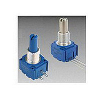
POT 10K OHM 5/8"
Manufacturer
Bourns Inc.
Series
95r
Type
Potentiometerr
Specifications of 95A1A-B24-B15
Number Of Turns
Single
Termination Style
Solder Lug
Temperature Coefficient
±1000ppm/°C
Resistance (ohms)
10K
Power (watts)
0.5W, 1/2W
Tolerance
±20%
Rotation
300°
Adjustment Type
Side Adjustment
Resistive Material
Conductive Plastic
Actuator Length
19.05mm
Actuator Type
Slotted Shaft
Actuator Diameter
6.35mm
Package / Case
Square - 0.625" L x 0.625" W x 0.500" H (15.88mm x 15.88mm x 12.70mm)
Resistance In Ohms
10.0K
Resistance
10kohm
Power Rating
1/2W
Tolerance (+ Or -)
20%
Technology
Cermet
Mounting Style
Panel
Operating Temp Range
-40C to 125C
Failure Rate
Not Required
Shaft Diameter (mm)
6.35mm
Product Diameter (mm)
Not Requiredmm
Product Length (mm)
31.75mm
Product Height (mm)
17.47mm
Product Depth (mm)
15.88mm
Taper
Linear
Element Type
Conductive Plastic
Shaft Type
Slotted
Shaft Length
3/4 in
Shaft Diameter
1/4 in
Operating Temperature Range
- 40 C to + 125 C
Product
Panel Mount Potentiometers
Lead Free Status / Rohs Status
Lead free / RoHS Compliant
Other names
95A1AB24B15
Q1082980
Q1082980


Contacts:
Power Rating (Resistive Load):
Contact Resistance (0.1 VDC-10 mA) ...............................................................................................................................10 milliohms nominal
Contact Bounce ...........................................................................................................................................................5 milliseconds maximum
Dielectric Withstanding Voltage (MIL-STD-202, Method 301)
Insulation Resistance ................................................................................................................................................. 1000 megohms minimum
Operating Temperature Range .................................................................................................................................................... 0 °C to +70 °C
Exposure Temperature Range ................................................................................................................................................-65 °C to +125 °C
Vibration (Dual Section).................................................................................................................................................................................. 8 G
Shock (Dual Section).................................................................................................................................................................................... 20 G
Rotational Life ................................................................................................................................................................................25,000 cycles
Moisture Resistance (MIL-STD-202, Method 106, Condition B)
Housing Material .......................................................................................................High temperature, fl ame retardant, thermosetting plastic
Actuating Torque (Each Section, Switch Module Only) .............................................................................. 3.53 to 10.59 N-cm (5 to 15 oz.-in.)
Running Torque (Out of Detent, 2-4 Module Assembly) ............................................................................. 0.21 to 1.41 N-cm (0.3 to 2 oz.-in.)
Detent ................................................................................................................................................................................CW or CCW standard
Actuation Angle ......................................................................................................................................................................................20 ° ±5 °
Contact Materials .................................................................................................................................................... Fine silver with gold overlay
Terminal Styles .............................................................................................................................................................................Solder lug only
Terminal Strength (Before and After Soldering Heat Exposure) .................................................................................... 0.9 kg (2 lbs.) minimum
NOTE:
1
At room ambient: +25 °C nominal and 50 % relative humidity nominal, except as noted.
Rotary Switch Specifi cations
Initial Electrical Characteristics
Environmental Characteristics
Mechanical Characteristics
DPST ........................................................................................................................................................N.O/N.O., N.C./N.C. or N.O./N.C.
DPDT ..........................................................................................................................................................2 N.O./N.C. (break before make)
DPST ..................................................................................... 2 A @ 125 volts RMS-60 Hz or 2 A @ 28 VDC, 1 A @ 250 volts RMS-60 Hz
DPDT .....................................................................................................................................1 A @ 125 volts RMS-60 Hz or 1 A @ 28 VDC
Sea Level ........................................................................................................................................................................1500 VAC minimum
Contact Resistance .................................................................................................................................................. 10 milliohms maximum
Contact Bounce ................................................................................................................................................... 0.1 millisecond maximum
Switch Actuating Torque (50% Duty cycle @ Rated Power Load) ........................................................... 1.41 to 4.94 N-cm (2 to 7 oz.-in.)
Contact Resistance ................................................................................................................................................ 100 milliohms maximum
Contact Resistance (0.1 VDC-10 mA) ..................................................................................................................... 10 milliohms maximum
Insulation Resistance (After 24 Hours @ Room Temperature) (500 VDC) ..............................................................100 megohms minimum
Standard Orientation ........................................................................................................................................ In-line with control terminals
Optional ....................................................................................................................................................Rotated 90 ° CCW from standard
97, 99 - 5/8 ” Square Single-Turn Panel Control with Rotary Switch
91, 92, 93, 94, 95, 96 - 5/8 ” Square Single-Turn Panel Control
Model 99 performance specifi cations do not apply to units subjected to printed circuit board cleaning procedures.
1
1
1
Customers should verify actual device performance in their specifi c applications.
Specifi cations are subject to change without notice.
Related parts for 95A1A-B24-B15
Image
Part Number
Description
Manufacturer
Datasheet
Request
R

Part Number:
Description:
POT SNGL TURN 7/8"10K OHM
Manufacturer:
Bourns Inc.
Datasheet:

Part Number:
Description:
Panel Mount Potentiometers 5/8 5K 10% Square Single Turn
Manufacturer:
Bourns Inc.
Datasheet:
Part Number:
Description:
POT 5K OHM 5/8" SQ 2W CERMET
Manufacturer:
Bourns Inc.
Datasheet:
Part Number:
Description:
Panel Mount Potentiometers 5/8 100K 10% Square Single Turn
Manufacturer:
Bourns Inc.
Datasheet:
Part Number:
Description:
RES,Non-Specified,10KOhms,10+/-% Tol,-150,150ppm-TC,5063-Case
Manufacturer:
Bourns Inc.
Datasheet:
Part Number:
Description:
RES,Non-Specified,100KOhms,10+/-% Tol,-150,150ppm-TC,5063-Case
Manufacturer:
Bourns Inc.
Datasheet:
Part Number:
Description:
RES,Non-Specified,500KOhms,20+/-% Tol,-1000,1000ppm-TC,5063-Case
Manufacturer:
Bourns Inc.
Datasheet:

Part Number:
Description:
PANEL CONTROL - 5/8" (16MM) ST-CP
Manufacturer:
Bourns Inc.
Datasheet:
Part Number:
Description:
RES,Non-Specified,10KOhms,10+/-% Tol,-150,150ppm-TC,5063-Case
Manufacturer:
Bourns Inc.
Datasheet:
Part Number:
Description:
PANEL CONTROL - 5/8" (16MM) ST-CP
Manufacturer:
Bourns Inc.
Datasheet:

Part Number:
Description:
Manufacturer:
Bourns, Inc.
Datasheet:
Part Number:
Description:
11mm Potentiometer
Manufacturer:
Bourns, Inc.
Datasheet: