3590S-2-103 Bourns Inc., 3590S-2-103 Datasheet
3590S-2-103
Manufacturer Part Number
3590S-2-103
Description
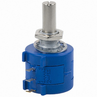
POT 10K OHM 7/8" WW 2W
Manufacturer
Bourns Inc.
Series
3590r
Datasheet
1.3590S-2-203L.pdf
(2 pages)
Specifications of 3590S-2-103
Tolerance
±5%
Termination Style
Solder Lug
Number Of Turns
10
Resistance (ohms)
10K
Power (watts)
2W
Temperature Coefficient
±50ppm/°C
Rotation
3600°
Adjustment Type
Side Adjustment
Resistive Material
Wirewound
Actuator Length
20.62mm
Actuator Type
Slotted Shaft
Actuator Diameter
6.30mm
Package / Case
Round - 0.875" Dia x 0.732" H (22.23mm x 18.60mm)
Resistance In Ohms
10.0K
Resistance
10 KOhms
Power Rating
2 Watts
Element Type
Wire Wound
Shaft Type
Slotted
Shaft Length
20.62 mm
Shaft Diameter
0.249 in
Dimensions
22 mm Dia. x 18.6 mm L
Product
Precision Potentiometers
Resolution
0.02 %
Track Resistance
10kohm
Track Taper
Linear
No. Of Turns
10
Resistance Tolerance
± 5%
Potentiometer Mounting
Bushing
No. Of Gangs
1
Leaded Process Compatible
No
Rohs Compliant
No
Lead Free Status / RoHS Status
Contains lead / RoHS non-compliant
Lead Free Status / RoHS Status
Lead free / RoHS Compliant, Contains lead / RoHS non-compliant
Available stocks
Company
Part Number
Manufacturer
Quantity
Price
Company:

Part Number:
3590S-2-103
Manufacturer:
BOURNS
Quantity:
6 000
Company:
Part Number:
3590S-2-103L
Manufacturer:
BOURNS
Quantity:
3 000
Company:
Part Number:
3590S-2-103L
Manufacturer:
BI
Quantity:
20 000
Company:
Part Number:
3590S-2-103L
Manufacturer:
BOURNS
Quantity:
20 000


Standard Resistance Range ........................................................................................................................................................................200 to 100 K ohms
Total Resistance Tolerance ............................................................................................................................................................................................... ±5 %
Independent Linearity .................................................................................................................................................................................................. ±0.25 %
Effective Electrical Angle ............................................................................................................................................................................... 3600 ° +10 °, -0 °
Absolute Minimum Resistance ..................................................................................................................... 1 ohm or 0.1 % maximum (whichever is greater)
Noise ................................................................................................................................................................................................ 100 ohms ENR maximum
Dielectric Withstanding Voltage (MIL-STD-202, Method 301)
Power Rating (Voltage Limited By Power Dissipation or 450 VAC, Whichever is Less)
Insulation Resistance (500 VDC) ..................................................................................................................................................... 1,000 megohms minimum
Resolution ............................................................................................................................................................................ See recommended part numbers
Operating Temperature Range ..................................................................................................................................................................... -40 °C to +125 °C
Storage Temperature Range ........................................................................................................................................................................ -55 °C to +125 °C
Temperature Coeffi cient Over Storage Temperature Range
Vibration ............................................................................................................................................................................................................................ 15 G
Shock ................................................................................................................................................................................................................................ 50 G
Load Life ................................................................................................................................................................................................... 1,000 hours, 2 watts
Rotational Life (No Load) ................................................................................................................................................................1,000,000 shaft revolutions
Moisture Resistance (MIL-STD-202, Method 103, Condition B)
IP Rating
Stop Strength .............................................................................................................................................................................45 N-cm (64 oz.-in.) minimum
Mechanical Angle .......................................................................................................................................................................................... 3600 ° +10 °, -0 °
Torque (Starting & Running) ................................................................................................................................. 0.35 N-cm (0.5 oz.-in.) maximum (unsealed)
Shaft Runout ..................................................................................................................................................................................... 0.13 mm (0.005 in.) T.I.R.
Lateral Runout ................................................................................................................................................................................... 0.20 mm (0.008 in.) T.I.R.
Shaft End Play ................................................................................................................................................................................... 0.25 mm (0.010 in.) T.I.R.
Shaft Radial Play ............................................................................................................................................................................... 0.13 mm (0.005 in.) T.I.R.
Pilot Diameter Runout ....................................................................................................................................................................... 0.08 mm (0.003 in.) T.I.R.
Backlash ............................................................................................................................................................................................................ 1.0 ° maximum
Weight ....................................................................................................................................................................................................... Approximately 19 G
Terminals ............................................................................................................................................................................................... Solder lugs or PC pins
Soldering Condition
Marking ....................................Manufacturer’s name and part number, resistance value and tolerance, linearity tolerance, wiring diagram, and date code.
Ganging (Multiple Section Potentiometers) ..................................................................................................................................................... 1 cup maximum
Hardware ...........................................................................................................One lockwasher and one mounting nut is shipped with each potentiometer.
NOTE: For Anti-rotation pin add 91 after confi guration dash number. Example: -2 becomes -291 to add AR pin.
1
2
At room ambient: +25 °C nominal and 50 % relative humidity nominal, except as noted.
Consult manufacturer for complete specifi cation details for resistances below 1k ohms.
Electrical Characteristics
Sea Level .............................................................................................................................................................................................. 1,500 VAC minimum
+40 °C........................................................................................................................................................................................................................ 2 watts
+125 °C........................................................................................................................................................................................................................ 0 watt
Environmental Characteristics
Wiper Bounce ............................................................................................................................................................................... 0.1 millisecond maximum
Wiper Bounce ............................................................................................................................................................................... 0.1 millisecond maximum
Total Resistance Shift ...................................................................................................................................................................................±2 % maximum
Total Resistance Shift ...................................................................................................................................................................................±5 % maximum
Total Resistance Shift ...................................................................................................................................................................................±2 % maximum
Sealed Versions (-3, -4, -7, and -8)................................................................................................................................................................................ IP 65
Unsealed Versions (-1 -2, -5, and -6) ............................................................................................................................................................................ IP 40
Mechanical Characteristics
Mounting............................................................................................................................................................................. 55-80 N-cm (5-7 lb.-in.) (plastic)
Wave Soldering...................................................................................96.5Sn/3.0Ag/0.5Cu solder with no-clean fl ux; 260 °C (500 °F) max. for 5 seconds
Wash processes ...................................................................................................................................................................................... Not recommended
Recommended Part Numbers
Manual Soldering ......................................................... 96.5Sn/3.0Ag/0.5Cu solid wire or no-clean rosin cored wire; 370 °C (700 °F) max. for 3 seconds
(Printed Circuit)
3590P-2-102L
3590P-2-202L
3590P-2-502L
3590P-2-103L
3590P-2-203L
3590P-2-503L
3590P-2-104L
3590S-2-102L
3590S-2-202L
3590S-2-502L
3590S-2-103L
3590S-2-203L
3590S-2-503L
3590S-2-104L
(Solder Lug)
1
1
1
3590S-1-102L
3590S-1-202L
3590S-1-502L
3590S-1-103L
3590S-1-203L
3590S-1-503L
3590S-1-104L
(Solder Lug)
Features
■
■
■
■
■
■
3590 - Precision Potentiometer
Bushing mount
Optional AR pin feature
Plastic or metal shaft and bushings
Wirewound
Solder lugs or PC pins
Sealable (Full body seal)
2
.........................................................................................................±50 ppm/°C maximum/unit
Resistance (Ω)
100,000
10,000
20,000
50,000
1,000
2,000
5,000
Resolution (%)
Customers should verify actual device performance in their specifi c applications.
.029
.023
.025
.020
.019
.013
.009
■
*RoHS Directive 2002/95/EC Jan 27 2003 including Annex
BOLDFACE LISTINGS ARE IN STOCK AND READILY
AVAILABLE THROUGH DISTRIBUTION.
FOR OTHER OPTIONS CONSULT FACTORY.
ROHS IDENTIFIER:
Designed for use in HMI applications
L = COMPLIANT
BLANK = NON-COMPLIANT
Specifi cations are subject to change without notice.
1.1 N-cm (1.5 oz.-in.) maximum (sealed)
90-113 N-cm (8-10 in.-lb.) (metal)
Related parts for 3590S-2-103
Image
Part Number
Description
Manufacturer
Datasheet
Request
R

Part Number:
Description:
POT 20K OHM 7/8" WW 2W
Manufacturer:
Bourns Inc.
Datasheet:
Part Number:
Description:
POT 10K OHM 7/8" WW 2W
Manufacturer:
Bourns Inc.
Datasheet:
Part Number:
Description:
POT 50K OHM 7/8" WW 2W
Manufacturer:
Bourns Inc.
Datasheet:
Part Number:
Description:
POT 1.0K OHM 7/8" WW 2W
Manufacturer:
Bourns Inc.
Datasheet:
Part Number:
Description:
POT 2.0K OHM 7/8" WW 2W
Manufacturer:
Bourns Inc.
Datasheet:
Part Number:
Description:
POT 5.0K OHM 7/8" WW 2W
Manufacturer:
Bourns Inc.
Datasheet:
Part Number:
Description:
POT 100K OHM 7/8" WW 2W
Manufacturer:
Bourns Inc.
Datasheet:
Part Number:
Description:
POT 500 OHM 7/8" WW 2W
Manufacturer:
Bourns Inc.
Datasheet:

Part Number:
Description:
POT 200 OHM 7/8" RD WW
Manufacturer:
Bourns Inc.
Datasheet:
Part Number:
Description:
POT 2K OHM 7/8" WW 2W
Manufacturer:
Bourns Inc.
Datasheet:
Part Number:
Description:
POT 5K OHM 7/8" WW 2W
Manufacturer:
Bourns Inc.
Datasheet:
Part Number:
Description:
POT 1K OHM 7/8" WW 2W
Manufacturer:
Bourns Inc.
Datasheet:
Part Number:
Description:
POT 20K OHM 7/8" WW 2W
Manufacturer:
Bourns Inc.
Datasheet:
Part Number:
Description:
POT 500 OHM 7/8" WW 2W
Manufacturer:
Bourns Inc.
Datasheet:
Part Number:
Description:
POT 50K OHM 7/8" WW 2W
Manufacturer:
Bourns Inc.
Datasheet:
3590S-2-103 Summary of contents
Page 1
... Consult manufacturer for complete specifi cation details for resistances below 1k ohms. Recommended Part Numbers (Printed Circuit) (Solder Lug) 3590P-2-102L 3590S-2-102L 3590S-1-102L 3590P-2-202L 3590S-2-202L 3590S-1-202L 3590P-2-502L 3590S-2-502L 3590S-1-502L 3590P-2-103L 3590S-2-103L 3590S-1-103L 3590P-2-203L 3590S-2-203L 3590S-1-203L 3590S-2-503L 3590P-2-503L 3590S-1-503L 3590P-2-104L 3590S-2-104L 3590S-1-104L Features ■ Bushing mount ■ ...
Page 2
Precision Potentiometer Product Dimensions -1, -3, -5, -7 Confi gurations 5.08 ± .38 (.200 ± .015) 5.08 ± .38 6.99 ± .38 (.200 ± .015) (.275 ± .015) 10.31 + .00/- .13 (.406+.000/-.005) 1 BUSHING DIAMETER 3 (SEE ...