6639S-1-103 Bourns Inc., 6639S-1-103 Datasheet
6639S-1-103
Manufacturer Part Number
6639S-1-103
Description
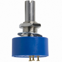
POT 10K OHM COND PLAST 1W
Manufacturer
Bourns Inc.
Series
6639r
Type
Potentiometerr
Datasheet
1.6639S-1-102.pdf
(2 pages)
Specifications of 6639S-1-103
Tolerance
±15%
Termination Style
Solder Turret
Number Of Turns
Single
Resistance (ohms)
10K
Power (watts)
1W
Temperature Coefficient
±500ppm/°C
Rotation
Continuous
Adjustment Type
Top Adjustment
Resistive Material
Conductive Plastic
Actuator Length
22.23mm
Actuator Type
Slotted Shaft
Actuator Diameter
6.34mm
Package / Case
Round - 0.875" Dia x 0.443" H (22.23mm x 11.25mm)
Resistance In Ohms
10.0K
Resistance
10 KOhms
Power Rating
1 Watt
Element Type
Conductive Plastic
Shaft Type
Round / Plain
Shaft Length
12.7 mm
Shaft Diameter
0.25 in
Dimensions
22.23 mm Dia. x 0.45 in L
Product
Precision Potentiometers
Angle, Mechanical
340 °
Diameter, Shaft
0.2497 "
Dielectric Strength
750 VAC
Insulation Resistance
500 Megohms (Min.) @ 500 VDC
Linearity
±2 %
Material, Element
Conductive Plastic
Mounting Type
Panel
Power, Rating
1 W
Resistance, Insulation
500 Megohms
Rotational Life
10,000,000 Shaft RevolutionsFeatures
Shaft Style
Radial
Taper
Linear
Temperature, Operating, Maximum
+125 °C
Temperature, Operating, Minimum
-40 °C
Termination
Rear Turret
Torque
0.5 Oz./in.
Voltage, Operating
750 VAC (Min.)
Weight
24 gm
Operating Temperature Range
–40°C to +125°C
Resistance Tolerance
±15%
Independent Linearity
±2%
Effective Electrical Angle
340° with Continuous Mechanical Angle
Mounting Style
Panel
Lead Free Status / RoHS Status
Lead free / RoHS Compliant
Lead Free Status / RoHS Status
Lead free / RoHS Compliant, Lead free / RoHS Compliant
Available stocks
Company
Part Number
Manufacturer
Quantity
Price
Company:

Part Number:
6639S-1-103
Manufacturer:
BOURNS
Quantity:
20 000
Company:
Part Number:
6639S-1-103
Manufacturer:
BOURNS
Quantity:
1 000


Standard Resistance Range ..............1 K to 100 K ohms ..................1 K to 100 K ohms
Total Resistance Tolerance ................±15 % ......................................±15 %
Independent Linearity ........................±2.0 % ......................................±2.0 %
Effective Electrical Angle ....................340 ° +3 °..................................340 ° +3 °
End Voltage ........................................0.5 % maximum ......................0.5 % maximum
Output Smoothness............................0.1 % ........................................0.1 %
Dielectric Withstanding Voltage (MIL-STD-202, Method 301)
Power Rating (Voltage Limited By Power Dissipation or 300 VAC, Whichever is Less)
Insulation Resistance (500 VDC) ........500 megohms minimum ..........500 megohms minimum
Resolution ..........................................Essentially infinite ....................Essentially infinite
Operating Temperature Range ..........+1 °C to +125 °C ......................-40 °C to +125 °C
Storage Temperature Range ..............-65 °C to +125 °C ....................-65 °C to +125 °C
Temperature Coefficient
Over Storage Temperature Range ......±500 ppm/°C maximum ..........±500 ppm/°C maximum
Vibration..............................................15 G ..........................................15 G
Shock..................................................50 G ..........................................50 G
Load Life ............................................1,000 hours, 1 watt ..................1,000 hours, 1 watt
Rotational Life (No Load)....................10,000,000 shaft revolutions ....10,000,000 shaft revolutions
Moisture Resistance (MIL-STD-202, Method 106)
IP Rating ............................................IP 40 ........................................IP 40
Mechanical Angle ..........................................................Continuous, Stops (340 ° +8 °, -0 °) available
Torque (Starting & Running)
Shaft Runout..................................................................................................0.13 mm (0.005 in.) T.I.R.
Lateral Runout ...............................................................................................0.08 mm (0.003 in.) T.I.R.
Shaft End Play ...............................................................................................0.13 mm (0.005 in.) T.I.R.
Shaft Radial Play ...........................................................................................0.13 mm (0.005 in.) T.I.R.
Pilot Diameter Runout .................................................................................0.06 mm (0.0025 in.) T.I.R.
Backlash ........................................................................................................................0.1 º maximum
Weight ........................................................18 gm (6539 Servo Mount), 24 gm (6639 Bushing Mount)
Terminals......................................................................................................................Rear Turret Type
Soldering Condition
Marking .................................................Manufacturer’s name and part number, resistance value and
Ganging (Multiple Section Pots) ..................................................................................1 cup maximum
Hardware (6639 only)..................................One lockwasher (H-37-2) and one mounting nut (H-38-2)
1
2
BOLDFACE LISTINGS ARE IN STOCK AND READILY
AVAILABLE THROUGH DISTRIBUTION.
FOR OTHER OPTIONS CONSULT FACTORY.
At room ambient: +25 °C nominal and 50 % relative humidity, except as noted.
2.82 N-cm (4.0 oz.-in.) max. at -40 °C.
Recommended Part Numbers
Electrical Characteristics
Environmental Characteristics
Mechanical Characteristics
Sea Level........................................750 VAC minimum ....................750 VAC minimum
+70 °C ............................................1.0 watt ....................................1.0 watt
+125 °C ..........................................0 watt........................................0 watt
Wiper Bounce ................................0.1 millisecond maximum ........0.1 millisecond maximum
Total Resistance Shift ....................±10 % ......................................±10 %
Voltage Ratio Shift..........................±0.5 % ......................................±0.5 %
Wiper Bounce ................................0.1 millisecond maximum ........0.1 millisecond maximum
Total Resistance Shift ....................±5 % ........................................±5 %
Voltage Ratio Shift..........................±0.5 % ......................................±0.5 %
Total Resistance Shift ....................±10 % ......................................±10 %
Total Resistance Shift ....................±10 % maximum ......................±10 % maximum
Total Resistance Shift ....................±15 % ......................................±15 %
Mounting.............................................................................170-200 N-cm (15-18 lb.-in.) maximum
Manual Soldering................................96.5Sn/3.0Ag/0.5Cu solid wire or no-clean rosin cored wire
Wave Soldering ........................................................96.5Sn/3.0Ag/0.5Cu solder with no-clean flux
Wash processes ..................................................................................................Not recommended
Part Number
6539S-1-102
6539S-1-502
6539S-1-103
2
.....................................................................0.40 N-cm (0.5 oz.-in.) max.
Resistance
1,000
5,000
10,000
1
(Ω)
1
6539 Servo Mount
1
tolerance, linearity tolerance, wiring diagram, and date code.
6639S-1-102 6639S-301-102
6639S-1-202
6639S-1-502 6639S-301-502
6639S-1-103 6639S-301-103
6639S-1-203
Continuous Turn
6539/6639 - Precision Potentiometer
Features
Essentially infinite resolution
Excellent rotational life
High quality, rugged construction
General purpose applications
Non-standard features available
Cost and space saving
Part Numbers
370 °C (700 °F) max. for 3 seconds
260 °C (500 °F) max. for 5 seconds
6639 Bushing Mount
Mechanical Stops
is shipped with potentiometer.
Customers should verify actual device performance in their specific applications.
Resistance
10,000
20,000
1,000
2,000
5,000
(Ω)
*RoHS Directive 2002/95/EC Jan 27 2003 including Annex
22.23
(.875)
6639
6539
DIA.
65/6639
(.875)
22.23
Product Dimensions
DIA.
Specifications are subject to change without notice.
CCW
11.25 ± .38
(.443±.015)
(.125)
3.18
1
(.062)
(.500 ± .015)
1.57
12.70 ± .38
TOLERANCES: EXCEPT WHERE NOTED
DECIMALS: .XX ±
FRACTIONS: ±1/64
DIMENSIONS:
(.125)
3.18
CLOCKWISE
30 °± 3 °
TYP.
CW
3
3/8 " - 32 UNEF
45 ° ± 5° ± (.010) CHAMFER
(IN.)
SLOT (.047) X (.063)
MM
2
2
(.2497+.0000/-.0003)
(.062)
(.020)
1.57
6.342+.000/-.008
.51
(.062)
WIPER
1.57
(.062)
(.4062+.000/-.002)
(.875 ± .03)
10.317+.000/-.051
22.23 ± .76
1.19
1.57
(.020)
DIA. SHAFT
1
REF
.51
.XXX ±
(.375 ± .031)
9.53 ± .79
.25
(.1248+.0000/-.0003)
3.170 +.000/-.008
1.60
(.750+.0000/-.0005)
19.050+ 000/-.012
45 ° ± 5 ° x (.010)
CHAMFER
(.010)
(.005)
.13
3
REF
DIA. SHAFT
.25
(.500 ± .031)
12.70 ± .79
CW
(.19)
4.83
DIA.
(.780)
19.81
R
DIA.
.25
Related parts for 6639S-1-103
Image
Part Number
Description
Manufacturer
Datasheet
Request
R

Part Number:
Description:
POT 2K OHM 7/8" RD 1W PLAS
Manufacturer:
Bourns Inc.
Datasheet:

Part Number:
Description:
POT 5K OHM COND PLAST 1W
Manufacturer:
Bourns Inc.
Datasheet:
Part Number:
Description:
POT 100K OHM 7/8" RD 1W PLAS
Manufacturer:
Bourns Inc.
Datasheet:
Part Number:
Description:
POT 20K OHM 7/8" RD 1W PLAS
Manufacturer:
Bourns Inc.
Datasheet:
Part Number:
Description:
POT 1K OHM COND PLAST 1W
Manufacturer:
Bourns Inc.
Datasheet:

Part Number:
Description:
POT 50K OHM 7/8" RD 1W PLAS
Manufacturer:
Bourns Inc.
Datasheet:
Part Number:
Description:
PRECISION POT-7/8" 22MM 1 TURN CP
Manufacturer:
Bourns Inc.
Datasheet:
Part Number:
Description:
POT 10K OHM 7/8" RD 1W PLAS
Manufacturer:
Bourns Inc.
Datasheet:

Part Number:
Description:
Manufacturer:
Bourns, Inc.
Datasheet:
Part Number:
Description:
11mm Potentiometer
Manufacturer:
Bourns, Inc.
Datasheet:
6639S-1-103 Summary of contents
Page 1
... Resistance (Ω) Continuous Turn Mechanical Stops 6639S-1-102 6639S-301-102 1,000 6639S-1-202 2,000 6639S-1-502 6639S-301-502 5,000 6639S-1-103 6639S-301-103 10,000 6639S-1-203 20,000 Customers should verify actual device performance in their specific applications. Product Dimensions 6539 3.170 +.000/-.008 12.70 ± .38 (.1248+.0000/-.0003) (.500 ± .015) 1 ...
Page 2
Precision Potentiometer Panel Thickness Dimensions (For Bushing Mount Only) 10.41 ± .08 DIA. (.410 ± .003) REV. 10/08 Specifications are subject to change without notice. Customers should verify actual device performance in their specific applications. HEX NUT 7.42 ...