ASMC-QAB2-TAC0E Avago Technologies US Inc., ASMC-QAB2-TAC0E Datasheet - Page 4
ASMC-QAB2-TAC0E
Manufacturer Part Number
ASMC-QAB2-TAC0E
Description
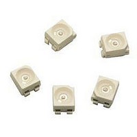
IC PWR LED INDICATOR 0.5W 4PLCC
Manufacturer
Avago Technologies US Inc.
Series
Envisium™r
Datasheet
1.ASMC-QAB2-TAC0E.pdf
(9 pages)
Specifications of ASMC-QAB2-TAC0E
Color
Amber
Current - Test
150mA
Luminous Flux @ Current - Test
6.6lm
Current - Max
150mA
Lumens @ Current - Max
7lm
Lumens/watt @ Current - Test
17lm/W
Voltage - Forward (vf) Typ
2.64V
Wavelength
593.5nm
Lens Style/size
Round, 2.4mm
Viewing Angle
120°
Mounting Type
Surface Mount
Package / Case
PLCC-4
Led Color
Amber
Luminous Intensity @ Test
6.5cd
Luminous Flux @ Test
6.6lm
Wavelength Typ
593.5nm
Forward Current @ Test
150mA
Forward Current If Max
300mA
Lead Free Status / RoHS Status
Lead free / RoHS Compliant


Figure 2. Relative Intensity Vs. Wavelength
Figure 6a. Maximum Forward Current Vs. Ambient Temperature.
Derated Based on T
4
Figure 4. Relative Intensity Vs. Forward Current
1.0
0.9
0.8
0.7
0.6
0.5
0.4
0.3
0.2
0.1
0.0
160
140
120
100
80
60
40
20
380
1.0
0
1.2
0.8
0.6
0.4
0.2
0
0
0
430
20
20
JMAX
AlInGaP Amber
480
Rθ
= 125°C, RT
40
JA
Rθ
DC FORWARD CURRENT - mA
= 110°C/W
AMBIENT TEMPERATURE (°C)
JA
40
530
= 130°C/W
60
WAVELENGTH - nm
J-A
=130 °C/W, 110°C/W and 100°C/W
580
60
80
630
100
80
AlInGaP Red Orange
Rθ
680
120
JA
= 100°C/W
100
140
730
160
120
780
Figure 6b. Maximum Forward Current Vs. Solder Point Temperature.
Derated Based on T
Figure 3. Forward Current Vs. Forward Voltage
Figure 5. Relative Intensity Vs. Temperature
160
140
120
100
350
300
250
200
150
100
50
80
60
40
20
0
0
-50
0
0
-25
20
AlInGaP Red Orange
JMAX
1
1.6
1.4
1.2
0.8
0.6
0.4
0.2
1
0
= 125°C, RT
SOLDER POINT TEMPERATURE (°C)
0
JUNCTION TEMPERATURE - °C
40
FORWARD VOLTAGE - V
2
25
JP
Rθ
= 60°C/W
60
JP
= 60°C/W
50
3
AlInGaP Amber
80
75
4
100
100
120
125
5
Related parts for ASMC-QAB2-TAC0E
Image
Part Number
Description
Manufacturer
Datasheet
Request
R

Part Number:
Description:
OPTOCOUPLER GATE DRV 2A 16-SOIC
Manufacturer:
Avago Technologies US Inc.
Datasheet:
Part Number:
Description:
OPTOCOUPLER 2CH 2.5A 16-SOIC
Manufacturer:
Avago Technologies US Inc.
Datasheet:

Part Number:
Description:
OPTOCOUPLER GATE DRV 0.4A 16SOIC
Manufacturer:
Avago Technologies US Inc.
Datasheet:

Part Number:
Description:
OPTOCOUPLER 2.0A 250KHZ 8-DIP
Manufacturer:
Avago Technologies US Inc.
Datasheet:

Part Number:
Description:
OPTOCOUPLER 2.0A 250KHZ GW 8-SMD
Manufacturer:
Avago Technologies US Inc.
Datasheet:

Part Number:
Description:
OPTOCOUPLER 2CH 15MBD 3.3V 8SOIC
Manufacturer:
Avago Technologies US Inc.
Datasheet:
Part Number:
Description:
OPTOCOUPLER DARL-OUT 8-DIP
Manufacturer:
Avago Technologies US Inc.
Datasheet:
Part Number:
Description:
OPTOCOUPLER IGBT DRIVE 0.4A 8DIP
Manufacturer:
Avago Technologies US Inc.
Datasheet:
Part Number:
Description:
OPTOCOUPLER DARL-OUT 8-DIP
Manufacturer:
Avago Technologies US Inc.
Datasheet:

Part Number:
Description:
OPTOCOUPLER 1CH 1MBS 8-SMD GW
Manufacturer:
Avago Technologies US Inc.
Datasheet:
Part Number:
Description:
OPTOCOUPLER GATE DRIVER 8-DIP
Manufacturer:
Avago Technologies US Inc.
Datasheet:

Part Number:
Description:
OPTOCOUPLER GATE DRIVER 8-SMD
Manufacturer:
Avago Technologies US Inc.
Datasheet:

Part Number:
Description:
OPTOCOUPLER PHOTOTRANS 4-SMD
Manufacturer:
Avago Technologies US Inc.
Datasheet:

Part Number:
Description:
OPTOCOUPLER W/BASE 6-DIP
Manufacturer:
Avago Technologies US Inc.
Datasheet:

Part Number:
Description:
ISOLAT 5KVRMS 4CH TRANS 16SMD GW
Manufacturer:
Avago Technologies US Inc.
Datasheet: