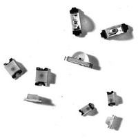
HSMB-C112 Avago Technologies US Inc., HSMB-C112 Datasheet - Page 5

HSMB-C112
Manufacturer Part Number
HSMB-C112
Description
LED CHIP SIC GAN BLUE RA MOUNT
Manufacturer
Avago Technologies US Inc.
Datasheet
1.HSMB-C112.pdf
(8 pages)
Specifications of HSMB-C112
Viewing Angle
130°
Color
Blue
Millicandela Rating
3.1mcd
Current - Test
10mA
Wavelength - Dominant
462nm
Wavelength - Peak
428nm
Voltage - Forward (vf) Typ
4V
Lens Type
Clear
Lens Style/size
Rectangle, 2mm x 1mm
Package / Case
1206 (3216 Metric)
Size / Dimension
3.20mm L x 1.00mm W
Height
1.50mm
Mounting Type
Surface Mount, Right Angle
Resistance Tolerance
462nm
Illumination Color
Blue
Wavelength
462 nm
Mounting Style
SMD/SMT
Lead Free Status / RoHS Status
Lead free / RoHS Compliant
Luminous Flux @ Current - Test
-
Lead Free Status / RoHS Status
Lead free / RoHS Compliant, Lead free / RoHS Compliant
Available stocks
Company
Part Number
Manufacturer
Quantity
Price
Company:
Part Number:
HSMB-C112
Manufacturer:
AVAGO
Quantity:
40 000
Blue Color Bin Limits
Tolerance: ±1 nm
Light Intensity (I
Tolerance: ± 15%
Notes:
1. Bin
2. The Iv binning specification set-up is for
Bin ID
A
B
C
D
Bin ID
A
B
C
D
E
F
G
H
J
K
L
M
N
P
Q
R
S
T
U
V
W
X
Y
classification of products. Products may
not be available in all categories. Please
contact your Avago srepresentative for
information regarding currently available
bins.
lowest allowable Iv binning only. There are
no upper Iv bin limits.
categories
Intensity (mcd)
Min.
0.11
0.18
0.29
0.45
0.72
1.10
1.80
2.80
4.50
7.20
11.20
18.00
28.50
45.00
71.50
112.50
180.00
285.00
450.00
715.00
1125.00
1800.00
2850.00
Dom. Wavelength (nm)
Min.
460
465
470
475
v
) Bin Limits
are
[1]
Max.
0.18
0.29
0.45
0.72
1.10
1.80
2.80
4.50
7.20
11.20
18.00
28.50
45.00
71.50
112.50
180.00
285.00
450.00
715.00
1125.00
1800.00
2850.00
4500.00
established
Max.
465
470
475
480
[1]
for
Figure 1. Relative intensity vs. wavelength.
Figure 3. Luminous intensity vs. forward current.
Figure 5. Relative intensity vs. angle for HSMx-C172, C192, C196, and C152.
100
80
60
40
20
100
0
90
80
70
60
50
40
30
20
10
400
120
100
0
80
60
40
20
-90
0
0
-80
450
I
F
-70
– FORWARD CURRENT – mA
WAVELENGTH – nm
500
5
-60
-50
550
10
-40
600
-30
-20
15
650
-10
ANGLE
700
0
20
10
20 30
Figure 2. Forward current vs. forward voltage.
Figure 4. Maximum forward current vs. ambient
temperature.
100
0.1
12
10
10
4
2
0
8
6
1
0
3.0
40
T
A
10
V
– AMBIENT TEMPERATURE – °C
50
3.2
F
20
– FORWARD VOLTAGE – V
60
30
3.4
70
40
80
3.6
50
60
90
3.8
70
80
4.0
90
100
4.2


