ASMT-QTC0-0AA02 Avago Technologies US Inc., ASMT-QTC0-0AA02 Datasheet
ASMT-QTC0-0AA02
Specifications of ASMT-QTC0-0AA02


Related parts for ASMT-QTC0-0AA02


ASMT-QTC0-0AA02 Summary of contents
Page 1
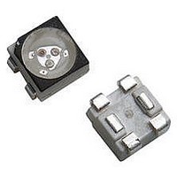
... ASMT-QTC0-0xxxx PLCC-4 Black Body Surface Mount Tricolor LED Data Sheet Description This family of SMT LEDs is packaged in the industry standard PLCC-4 package with additional heat sinking ca- pability enabling driven at even higher current. These SMT LEDs have high brightness and reliability per- formance and are designed to work under a wide range of environmental conditions ...
Page 2
... Table 1. Device Selection Guide Part Number ASMT-QTC0-0xxxx Color 1 - Red Min. Iv @20mA Part Number Bin ID (mcd) ASMT-QTC0-0AA02 S1 180 Notes: 1. The luminous intensity IV, is measured at the mechanical axis of the LED package. The actual peak of the spatial radiation pattern may not be aligned with this axis. 2. Tolerance = ± 2.00 ± ...
Page 3
Part Numbering System –Q T C0– Table 2. Absolute Maximum Ratings (T Parameter [1] DC forward current [2] Peak forward current Power dissipation Reverse voltage Maximum ...
Page 4
Table 4. Electrical Characteristics (T = 25°C) A Forward Voltage, [1] V (V) F Color Min Typ. Max. Red 1.80 2.10 2.40 Green 2.80 3.20 3.90 Blue 2.80 3.20 3.90 Note: 1. Tolerance ± 0.1V 1.0 InGaN Gre InGaN Blue ...
Page 5
AlInGaP 50 40 InGaN AMBIENT TEMPERATURE (°C) Figure 5a. Maximum forward current vs. ambient temperature. Derated based on T MAX = 125°C.(3 chips 0.9 0.8 0.7 0.6 0.5 0.4 ...
Page 6
Package (1) (4) Marking Figure 10. Recommended soldering land pattern. 20 SEC. MAX. 240°C MAX. 3°C/SEC. MAX. 100-150°C 3°C/SEC. MAX. 120 SEC. MAX. 60-150 SEC. TIME Figure 11. Recommended leaded reflow soldering profile Note: For detail information on ...
Page 7
Figure 13. Carrier Tape Dimension Figure 14. Reel Dimension USER FEED DIRECTION PRINTED LABEL Figure 15. Reeling Orientation 7 1.75 ± 0.10 + 0.10 1. 1.50 ± 0.25 ...
Page 8
Intensity Bin Select ( Individual reel will contain parts from 1 half bin only Min Iv Bin (Minimum Intensity Bin) X Red Green Number of Half bin from ...
Page 9
Packaging Option ( Option Test Current Package Type 2 20mA Top mount CIE 1931 - Chromaticity Diagram 0.90 0. 0.70 Green 0.60 0.50 0.40 0.30 0.20 Blue 0. 0.00 0.00 0.10 0.20 0.30 9 ...
Page 10
Handling Precaution The encapsulation material of the product is made of silicone for better reliability of the product. As silicone is a soft material, please do not press on the silicone or poke a sharp object onto the silicone. These ...