HLMP-3554 Avago Technologies US Inc., HLMP-3554 Datasheet - Page 3
HLMP-3554
Manufacturer Part Number
HLMP-3554
Description
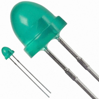
LED 5MM 565NM GREEN DIFF LO PRO
Manufacturer
Avago Technologies US Inc.
Datasheet
1.HLMP-3351.pdf
(9 pages)
Specifications of HLMP-3554
Viewing Angle
50°
Package / Case
Radial - 2 Lead
Color
Green
Millicandela Rating
6.7mcd
Current - Test
10mA
Wavelength - Dominant
569nm
Wavelength - Peak
565nm
Voltage - Forward (vf) Typ
2.1V
Lens Type
Diffused, Green Tinted
Lens Style/size
Round, 5mm, T-1 3/4
Height
5.84mm
Mounting Type
Through Hole
Resistance Tolerance
569nm
Led Size
T-1 3/4
Illumination Color
Green
Lens Color/style
Tinted Non-Diffused
Operating Voltage
2.1 V
Wavelength
569 nm
Luminous Intensity
6.7 mcd
Operating Current
10 mA
Lens Dimensions
5 mm
Lens Shape
Dome
Maximum Operating Temperature
+ 100 C
Minimum Operating Temperature
- 20 C
Mounting Style
Through Hole
Lead Free Status / RoHS Status
Lead free / RoHS Compliant
Luminous Flux @ Current - Test
-
Lead Free Status / Rohs Status
Lead free / RoHS Compliant
Other names
516-1318
Available stocks
Company
Part Number
Manufacturer
Quantity
Price
Company:

Part Number:
HLMP-3554
Manufacturer:
AVAGO
Quantity:
40 000
Company:
Part Number:
HLMP-3554
Manufacturer:
AVAGO
Quantity:
50 000
Company:
Part Number:
HLMP-3554-E0002
Manufacturer:
AVAGO
Quantity:
50 000
Company:
Part Number:
HLMP-3554-E00R1
Manufacturer:
AVAGO
Quantity:
50 000


Absolute Maximum Ratings at T
Notes:
1. See Figure 10 (High Efficiency Red), 15 (Yellow), or 20 (Green) to establish pulsed operating conditions.
2. For High Efficiency Red and Green Series, derate linearly from 50°C at 0.5 mA/°C. For Red and Yellow Series, derate linearly from 50°C at
3. For High Efficiency Red and Green Series, derate power linearly from 25°C at 1.8 mW/°C. For Red and Yellow Series, derate power linearly from 50°C
4. The transient peak current is the maximum non-recurring peak current that can be applied to the device without damaging the LED die and
Figure 1. Relative intensity vs. wavelength.
3
Parameter
Peak Forward Current
Average Forward Current
DC Current
Power Dissipation
Reverse Voltage (I
Transient Forward Current
Operating Temperature Range
Storage Temperature Range
Wave Soldering Temperature
[1.59 mm (0.063 in.) from Body]
Solder Dipping Temperature
[1.59 mm (0.063 in.) from Body]
0.2 mA/°C.
at 1.6 mW/°C.
wirebond. It is not recommended that the device be operated at peak current beyond the peak forward current listed in the Absolute Maximum
Ratings.
1.0
0.5
500
GREEN
[2]
R
[3]
= 100 μA)
550
[1]
[4]
YELLOW
(10 μs Pulse)
A
= 25°C
EFFICIENCY
600
WAVELENGTH – nm
HIGH
RED
650
RED
3350 Series
90
25
30
135
5
500
-40 to +100
-40 to +100
700
T
A
= 25°C
750
250°C for 3 seconds
260°C for 5 seconds
3450 Series
60
20
20
85
5
500
-40 to +100
-40 to +100
3550 Series
90
25
30
135
5
500
-20 to +100
-40 to +100
Units
mA
mA
mA
mW
V
mA
°C
Related parts for HLMP-3554
Image
Part Number
Description
Manufacturer
Datasheet
Request
R

Part Number:
Description:
LED 5MM 639NM RED WATER CLEAR
Manufacturer:
Avago Technologies US Inc.
Datasheet:

Part Number:
Description:
LED 5MM 635NM HE RED WATER CLEAR
Manufacturer:
Avago Technologies US Inc.
Datasheet:

Part Number:
Description:
LED 3MM 569NM GREEN DIFF
Manufacturer:
Avago Technologies US Inc.
Datasheet:

Part Number:
Description:
LED LT BAR 19.05X3.81MM SGL YLW
Manufacturer:
Avago Technologies US Inc.
Datasheet:

Part Number:
Description:
LED Lamp
Manufacturer:
Avago Technologies US Inc.
Datasheet:

Part Number:
Description:
LED 5MM ALINGAP 590NM AMB 15DEG
Manufacturer:
Avago Technologies US Inc.
Datasheet:

Part Number:
Description:
LED T1 3/4 5MM WHT PREC OPT PREF
Manufacturer:
Avago Technologies US Inc.
Datasheet:
Part Number:
Description:
LED, T-1 3/4, RED, 8.6MCD, 626NM
Manufacturer:
Avago Technologies US Inc.
Datasheet:

Part Number:
Description:
LED 5MM FLAT TOP INGAN WHITE
Manufacturer:
Avago Technologies US Inc.
Datasheet:
Part Number:
Description:
LED 5MM FLAT TOP INGAN WHITE
Manufacturer:
Avago Technologies US Inc.
Datasheet:
Part Number:
Description:
LED 5MM FLAT TOP INGAN WHITE
Manufacturer:
Avago Technologies US Inc.
Datasheet:
Part Number:
Description:
LED 5MM FLAT TOP INGAN WHITE
Manufacturer:
Avago Technologies US Inc.
Datasheet:

Part Number:
Description:
LED
Manufacturer:
Avago Technologies US Inc.
Datasheet:

Part Number:
Description:
LED T 1 3/4 OR 5MM AMBER
Manufacturer:
Avago Technologies US Inc.
Datasheet:

Part Number:
Description:
LED T1-3/4 SUPER BRIGHT GREEN
Manufacturer:
Avago Technologies US Inc.