HLMP-EL08-VY000 Avago Technologies US Inc., HLMP-EL08-VY000 Datasheet - Page 8
HLMP-EL08-VY000
Manufacturer Part Number
HLMP-EL08-VY000
Description
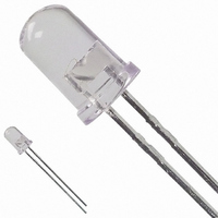
LED 5MM 592NM AMBER WATER CLEAR
Manufacturer
Avago Technologies US Inc.
Type
Uni-Colorr
Datasheet
1.HLMP-EL15-VY0DD.pdf
(15 pages)
Specifications of HLMP-EL08-VY000
Viewing Angle
8°
Package / Case
Radial - 2 Lead
Color
Amber
Luminous Flux @ Current - Test
500 mlm
Millicandela Rating
8100mcd
Current - Test
20mA
Wavelength - Dominant
590nm
Wavelength - Peak
592nm
Voltage - Forward (vf) Typ
2.02V
Lens Type
Clear
Lens Style/size
Round, 5mm, T-1 3/4
Height
8.71mm
Mounting Type
Through Hole
Resistance Tolerance
590nm
Led Size
T-1 3/4
Illumination Color
Amber
Lens Color/style
Untinted Non-Diffused
Operating Voltage
2.02 V
Wavelength
590 nm
Luminous Intensity
4200 mcd to 12000 mcd
Operating Current
20 mA
Lens Dimensions
5 mm
Lens Shape
Dome
Maximum Operating Temperature
+ 100 C
Minimum Operating Temperature
- 40 C
Mounting Style
Through Hole
Package Type
T-1 3/4
Emitting Color
Amber
Test Current (it)
20mA
Forward Current
50mA
Dominant Wave Length
590nm
Luminous Flux
0.5lm
Forward Voltage
2.4V
Product Length (mm)
5.8mm
Product Height (mm)
8.71mm
Product Depth (mm)
5.8mm
Mounting
Through Hole
Peak Wavelength
592nm
Shape Type
Circular
Chip Material
AlGaInP
Main Category
Standard LED
Number Of Elements
1
Pin Count
2
Operating Temperature Classification
Industrial
Operating Temp Range
-40C to 100C
Reverse Voltage
20V
Lead Free Status / RoHS Status
Lead free / RoHS Compliant
Lead Free Status / RoHS Status
Lead free / RoHS Compliant, Lead free / RoHS Compliant
Other names
516-1378
Available stocks
Company
Part Number
Manufacturer
Quantity
Price
Company:

Part Number:
HLMP-EL08-VY000
Manufacturer:
AVAGO
Quantity:
40 000
Company:
Part Number:
HLMP-EL08-VY000
Manufacturer:
AVAGO
Quantity:
50 000


Absolute Maximum Ratings at T
DC Forward Current
Peak Pulsed Forward Current
Average Forward Current
Reverse Voltage (I
LED Junction Temperature ....................................................................................... 130°C
Operating Temperature .........................................................................-40°C to +100°C
Storage Temperature ..............................................................................-40°C to +100°C
Notes:
1. Derate linearly as shown in Figure 4.
2. For long term performance with minimal light output degradation, drive currents between 10
3. Operating at currents below 1 mA is not recommended. Please contact your local representa-
Electrical/Optical Characteristics at T
Parameter
Forward Voltage
Reverse Voltage
Peak Wavelength:
Spectral Halfwidth
Speed of Response
Capacitance
Thermal Resistance
Luminous Efficacy
Luminous Flux
Luminous Efficiency
Note:
1. The radiant intensity, I
is the luminous efficacy in lumens/watt.
2. h
8
Amber
Orange
Red-Orange
Red
Orange (λ
Red-Orange (λ
Red (λ
Amber (λ
Orange (λ
Red-Orange (λ
Red (λ
Amber (λ
Orange (λ
Red-Orange (λ
Red (λ
mA and 30 mA are recommended. For more information on recommended drive conditions,
please refer to Application Brief I-024.
tive for further information.
Amber (λ
e
= j
d
d
d
V
= 626 nm)
= 626 nm)
= 626 nm)
/ I
d
d
d
d
d
F
d
= 590 nm)
= 590 nm)
= 605 nm)
= 605 nm)
= 605 nm)
x V
= 590 nm)
F
d
d
d
, where j
= 615 nm)
= 615 nm)
= 615 nm)
[1]
R
[2]
= 100 µA) ........................................................................................ 5 V
e
[1,2,3]
, in watts per steradian, may be found from the equation I
V
is the emitted luminous flux, I
[3]
..................................................................................... 50 mA
.................................................................................. 30 mA
[2,3]
A
.......................................................................100 mA
= 25°C
A
Symbol
V
V
λ
∆λ
t
C
Rθ
h
j
h
= 25°C
F
R
s
PEAK
v
v
e
J-PIN
1/2
F
is electrical forward current and V
Min.
5
Typ.
2.02
1.98
1.94
1.90
20
592
609
621
635
17
20
40
240
480
370
260
150
500
12
13
13
13
e
= I
Max.
2.4
v
/h
v
, where I
F
is the forward voltage.
Units
V
V
nm
nm
ns
pF
°C/W
lm/W
mlm
lm/W
v
is the luminous intensity in candelas and h
Test Conditions
I
I
Peak of Wavelength of
Spectral Distribution
at I
Wavelength Width at
Spectral Distribution
1
I
Exponential Time
Constant, e
V
LED Junction-to-Cathode
Lead
Emitted Luminous
Power/Emitted Radiant
Power
I
Emitted Luminous
Flux/Electrical Power
F
F
F
F
/
F
2
= 20 mA
= 100 µA
= 20 mA
= 20 mA
= 0, f = 1 MHz
F
Power Point at
= 20 mA
-t/ts
v
Related parts for HLMP-EL08-VY000
Image
Part Number
Description
Manufacturer
Datasheet
Request
R

Part Number:
Description:
LED 5MM ALINGAP 590NM AMB 6DEG
Manufacturer:
Avago Technologies US Inc.
Datasheet:

Part Number:
Description:
LED 5MM ALINGAP 590NM AMB 6DEG
Manufacturer:
Avago Technologies US Inc.
Datasheet:
Part Number:
Description:
LED 5MM ALINGAP 590NM AMB 6DEG
Manufacturer:
Avago Technologies US Inc.
Datasheet:

Part Number:
Description:
LED 5MM ALINGAP 590NM AMB 6DEG
Manufacturer:
Avago Technologies US Inc.
Datasheet:
Part Number:
Description:
LED ROUND 5MM 590NM AMBER 8DEG
Manufacturer:
Avago Technologies US Inc.
Datasheet:
Part Number:
Description:
LED ROUND 5MM 590NM AMBER 8DEG
Manufacturer:
Avago Technologies US Inc.
Datasheet:
Part Number:
Description:
LED ROUND 5MM 590NM AMBER 8DEG
Manufacturer:
Avago Technologies US Inc.
Datasheet:
Part Number:
Description:
LED 5MM ALINGAP 590NM AMB 6DEG
Manufacturer:
Avago Technologies US Inc.
Datasheet:
Part Number:
Description:
LED AMBER 590NM
Manufacturer:
Avago Technologies US Inc.
Datasheet:
Part Number:
Description:
LED 5MM ALINGAP 590NM AMB 6DEG
Manufacturer:
Avago Technologies US Inc.
Datasheet:
Part Number:
Description:
LED 5MM ALINGAP 590NM AMB 6DEG
Manufacturer:
Avago Technologies US Inc.
Datasheet:
Part Number:
Description:
LED T 1 3/4 OR 5MM AMBER
Manufacturer:
Avago Technologies US Inc.
Datasheet:
Part Number:
Description:
LED 5MM ALINGAP 590NM AMB 6DEG
Manufacturer:
Avago Technologies US Inc.
Datasheet:

Part Number:
Description:
LAMP,5MM,ALINGAP,AMB,8DEG
Manufacturer:
Avago Technologies US Inc.
Part Number:
Description:
General Purpose Visible Dome-Style LED,Amber,Clear,LED-2b
Manufacturer:
Avago Technologies US Inc.
Datasheet: