HSMC-C280 Avago Technologies US Inc., HSMC-C280 Datasheet - Page 3
HSMC-C280
Manufacturer Part Number
HSMC-C280
Description
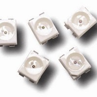
LED CHIP ALINGAP RED TOP MOUNT
Manufacturer
Avago Technologies US Inc.
Datasheet
1.HSMG-C280.pdf
(8 pages)
Specifications of HSMC-C280
Color
Red
Millicandela Rating
90mcd
Current - Test
20mA
Wavelength - Dominant
626nm
Wavelength - Peak
637nm
Voltage - Forward (vf) Typ
1.9V
Lens Type
Diffused
Lens Style/size
Rectangle, 1mm x 0.5mm
Package / Case
0402 (1005 Metric)
Size / Dimension
1.00mm L x 0.05mm W
Height
0.40mm
Viewing Angle
130°
Mounting Type
Surface Mount
Resistance Tolerance
626nm
Mounting Style
SMD/SMT
Lead Free Status / RoHS Status
Lead free / RoHS Compliant
Luminous Flux @ Current - Test
-
Lead Free Status / RoHS Status
Lead free / RoHS Compliant, Lead free / RoHS Compliant
Available stocks
Company
Part Number
Manufacturer
Quantity
Price
Company:

Part Number:
HSMC-C280
Manufacturer:
AVAGO
Quantity:
40 000


Absolute Maximum Ratings at T
Parameter
DC Forward Current
Peak Pulsing Current
Power Dissipation
Reverse Voltage (I
LED Junction Temperature
Operating Temperature Range
Storage Temperature Range
Soldering Temperature
Notes:
1. Derate linearly as shown in Figure 4.
2. Pulse condition of 1/10 duty and 0.1 ms width.
Electrical Characteristics at T
HSMA-C280
HSMC-C280
HSML-C280
HSMT-C280
HSMG-C280
HSMS-C280
HSMY-C280
Optical Characteristics at T
HSMA-C280
HSMC-C280
HSML-C280
HSMT-C280
HSMG-C280
HSMS-C280
HSMY-C280
N otes:
1. The luminous intensity, I
2. The dominant wavelength, λ
. θ
Part Number
Part Number
1/2
is the off-axis angle where the luminous intensity is 1/2 the peak intensity.
R
= 100 µA)
[1]
[2]
V
Color
AS Amber
AS Red
Orange
AS Deep Red
GaP Green
HER
GaP Yellow
, is measured at the peak of the spatial radiation pattern which may not be aligned with the mechanical axis of the lamp package.
d
, is derived from the CIE Chromatically Diagram and represents the perceived color of the device.
A
Forward Voltage
V
@ I
Typ.
1.9
1.9
1.9
1.9
2.2
2.1
2.1
= 25˚C
A
F
= 25˚C
(Volts)
F
A
= 20 mA
= 25˚C
Max.
2.4
2.4
2.4
2.4
2.6
2.6
2.6
Luminous
Intensity
I
@ 20 mA
Min.
28.5
28.5
28.5
11.2
4.5
2.8
2.8
V
(mcd)
[1]
HSMA/C/L/T-C280
25
100
60
5
95
–0 to +85
–40 to +85
See IR soldering profile (Figure 6 & 7)
Typ.
90
90
90
0
15
10
8
Reverse Breakdown
V
@ I
Min.
5
5
5
5
5
5
5
R
(Volts)
R
= 100 µA
Peak
Wavelength
λ
Typ.
595
67
609
660
570
60
589
peak
(nm)
Color,
Dominant
Wavelength
λ
Typ.
592
626
605
69
572
626
586
HSMG/S/Y-C280
20
100
52
5
95
–0 to +85
–40 to +85
d [2]
Capacitance C
(pF), V
f = 1 MHz
Typ.
11
15
15
45
9
5
6
(nm)
F
= 0,
Viewing
Angle
2 θ
Degrees
Typ.
10
10
10
10
10
10
10
1/2
[3]
Thermal
Resistance
Rθ
Typ.
00
00
00
00
250
250
250
J–PIN
Luminous
Efficacy
η
(lm/w)
Typ.
480
155
155
70
595
145
500
Units
mA
mA
mW
V
˚C
˚C
˚C
V
(˚C/W)
Related parts for HSMC-C280
Image
Part Number
Description
Manufacturer
Datasheet
Request
R

Part Number:
Description:
LED 637NM RED REVERSE MNT SMD
Manufacturer:
Avago Technologies US Inc.
Datasheet:

Part Number:
Description:
LED CHIP ALINGAP RED TOP MOUNT
Manufacturer:
Avago Technologies US Inc.
Datasheet:

Part Number:
Description:
LED 635NM RED 2-PLCC SMD
Manufacturer:
Avago Technologies US Inc.
Datasheet:

Part Number:
Description:
LED 635NM RED 2-PLCC SMD
Manufacturer:
Avago Technologies US Inc.
Datasheet:

Part Number:
Description:
LED 637NM RED DIFF 0603 SMD
Manufacturer:
Avago Technologies US Inc.
Datasheet:

Part Number:
Description:
LED 637NM RED DIFF 0805 SMD
Manufacturer:
Avago Technologies US Inc.
Datasheet:

Part Number:
Description:
LED IND 635NM RED TOP MT 2PLCC
Manufacturer:
Avago Technologies US Inc.
Datasheet:
Part Number:
Description:
LED IND 635NM RED TOP MT 2PLCC
Manufacturer:
Avago Technologies US Inc.
Datasheet:
Part Number:
Description:
LED IND 635NM RED TOP MT 2PLCC
Manufacturer:
Avago Technologies US Inc.
Datasheet:
Part Number:
Description:
LED IND 635NM RED TOP MT 4PLCC
Manufacturer:
Avago Technologies US Inc.
Datasheet:

Part Number:
Description:
LED CHIP ALINGAP RED TOP MOUNT
Manufacturer:
Avago Technologies US Inc.
Datasheet:

Part Number:
Description:
LED CHIP ALINGAP RED RA MNT
Manufacturer:
Avago Technologies US Inc.
Datasheet:

Part Number:
Description:
LED IND 635NM RED TOP MT 4PLCC
Manufacturer:
Avago Technologies US Inc.
Datasheet:

Part Number:
Description:
LED 630NM RED DIFF 0805 SMD
Manufacturer:
Avago Technologies US Inc.
Datasheet:
Part Number:
Description:
LED CHIP ALINGAP RED TOP MNT SMD
Manufacturer:
Avago Technologies US Inc.
Datasheet: