HLMP-K105 Avago Technologies US Inc., HLMP-K105 Datasheet - Page 3
HLMP-K105
Manufacturer Part Number
HLMP-K105
Description
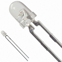
LED 3MM 645NM RED WATER CLEAR
Manufacturer
Avago Technologies US Inc.
Type
Uni-Colorr
Datasheet
1.HLMP-D101.pdf
(8 pages)
Specifications of HLMP-K105
Viewing Angle
45°
Package / Case
Radial - 2 Lead
Color
Red
Millicandela Rating
65mcd
Current - Test
20mA
Wavelength - Dominant
637nm
Wavelength - Peak
645nm
Voltage - Forward (vf) Typ
1.8V
Lens Type
Clear
Lens Style/size
Round, 3mm, T-1
Height
4.70mm
Mounting Type
Through Hole
Resistance Tolerance
637nm
Led Size
T-1
Illumination Color
Red
Lens Color/style
Water Clear
Operating Voltage
1.8 V
Wavelength
645 nm
Luminous Intensity
65 mcd
Mounting Style
Through Hole
Package Type
T-1
Emitting Color
Red
Test Current (it)
20mA
Forward Current
30mA
Dominant Wave Length
637nm
Forward Voltage
2.2V
Product Length (mm)
3.43mm
Product Height (mm)
4.7mm
Product Depth (mm)
3.43mm
Mounting
Through Hole
Peak Wavelength
645nm
Shape Type
Circular
Chip Material
GaAlAs
Main Category
Standard LED
Number Of Elements
1
Pin Count
2
Operating Temperature Classification
Commercial
Operating Temp Range
-20C to 100C
Reverse Voltage
5V
Power Dissipation
87mW
Lens Dimensions
3.17x3.17x3.56mm
Lead Free Status / RoHS Status
Lead free / RoHS Compliant
Luminous Flux @ Current - Test
-
Lead Free Status / Rohs Status
Lead free / RoHS Compliant
Other names
516-1314
Available stocks
Company
Part Number
Manufacturer
Quantity
Price
Company:

Part Number:
HLMP-K105
Manufacturer:
QUALITYT
Quantity:
500
Company:
Part Number:
HLMP-K105
Manufacturer:
AVAGO
Quantity:
40 000
Company:
Part Number:
HLMP-K105-J0002
Manufacturer:
AVAGO
Quantity:
40 000
Company:
Part Number:
HLMP-K105-J0002
Manufacturer:
AVAGO
Quantity:
50 000


Absolute Maximum Ratings at T
Notes:
1. Maximum I
2. Refer to Figure 6 to establish pulsed operating conditions.
3. Derate linearly as shown in Figure 5.
4. The transient peak current is the maximum non-recurring peak current the device can withstand without damaging the LED die and wire bonds.
Electrical/Optical Characteristics at T
Notes:
1. The dominant wavelength, λ
2. The radiant intensity, I
3. HLMP-D101.
4. HLMP-D105.
5. HLMP-K101/-K105.
3
Parameter
Peak Forward Current
Average Forward Current
DC Current
Power Dissipation
Reverse Voltage (I
Transient Forward Current (10 μs Pulse)
LED Junction Temperature
Operating Temperature Range
Storage Temperature Range
Symbol
V
V
λ
λ
Δλ
τ
C
Rθ
η
S
p
d
F
R
V
It is not recommended that the device be operated at peak currents beyond the Absolute Maximum Peak Forward Current.
J-PIN
luminous efficacy in lumens/watt.
1
/
2
[3]
PEAK
Description
Forward Voltage
Reverse Breakdown Voltage
Peak Wavelength
Dominant Wavelength
Spectral Line Halfwidth
Speed of Response
Capacitance
Thermal Resistance
Luminous Efficacy
at f = 1 kHz, DF = 6.7%.
R
= 100 μA)
[1,2]
e
, in watts per steradian, may be found from the equation I
[2]
d
, is derived from the CIE chromaticity diagram and represents the color of the device.
A
= 25°C
A
= 25°C
[4]
Min.
5.0
Typ.
1.8
15.0
645
637
20
30
30
260
210
290
80
[3]
[4]
[5]
e
= l
Max.
2.2
V
/η
V
, where I
V
is the luminous intensity in candelas and η
Unit
V
V
nm
pF
nm
nm
ns
°C/W
Im/W
Value
300 mA
20 mA
30 mA
87 mW
5 V
500 mA
110°C
-20 to +100°C
-40 to +100°C
Test Condition
I
I
Measurement at Peak
Note 1
Exponential Time
Constant, e
V
Junction to Cathode
Lead
Note 2
F
R
F
= 20 mA
= 100 μA
= 0, f = 1 MHz
-t
/T
S
V
is
Related parts for HLMP-K105
Image
Part Number
Description
Manufacturer
Datasheet
Request
R

Part Number:
Description:
LED 3MM 569NM GREEN DIFF
Manufacturer:
Avago Technologies US Inc.
Datasheet:

Part Number:
Description:
LED 5MM 635NM HE RED WATER CLEAR
Manufacturer:
Avago Technologies US Inc.
Datasheet:

Part Number:
Description:
LED 5MM 639NM RED WATER CLEAR
Manufacturer:
Avago Technologies US Inc.
Datasheet:

Part Number:
Description:
LED LT BAR 8.89X3.81MM SGL GREEN
Manufacturer:
Avago Technologies US Inc.
Datasheet:

Part Number:
Description:
LED LT BAR 19.05X3.81MM SGL YLW
Manufacturer:
Avago Technologies US Inc.
Datasheet:

Part Number:
Description:
LED Lamp
Manufacturer:
Avago Technologies US Inc.
Datasheet:

Part Number:
Description:
LED 5MM FLAT TOP INGAN WHITE
Manufacturer:
Avago Technologies US Inc.
Datasheet:
Part Number:
Description:
LED 5MM FLAT TOP INGAN WHITE
Manufacturer:
Avago Technologies US Inc.
Datasheet:
Part Number:
Description:
LED 5MM FLAT TOP INGAN WHITE
Manufacturer:
Avago Technologies US Inc.
Datasheet:
Part Number:
Description:
LED 5MM FLAT TOP INGAN WHITE
Manufacturer:
Avago Technologies US Inc.
Datasheet:

Part Number:
Description:
LED DOME 5V 635NM HER DFF RA AXL
Manufacturer:
Avago Technologies US Inc.
Datasheet:

Part Number:
Description:
LED DOME 5V 565NM GN DIFF RA AXL
Manufacturer:
Avago Technologies US Inc.
Datasheet:

Part Number:
Description:
LED DOME 583NM YLW DIFF RA AXIAL
Manufacturer:
Avago Technologies US Inc.
Datasheet:

Part Number:
Description:
LED 5MM GAP GRN RA HOUSING TH
Manufacturer:
Avago Technologies US Inc.
Datasheet:

Part Number:
Description:
LED 3MM GAP DIFF RED RA HOUSING
Manufacturer:
Avago Technologies US Inc.
Datasheet: