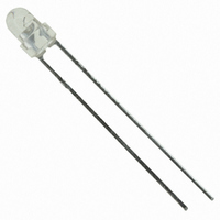
HLMP-NL06 Avago Technologies US Inc., HLMP-NL06 Datasheet

HLMP-NL06
Specifications of HLMP-NL06
HLMP-NL06
Available stocks
Related parts for HLMP-NL06
HLMP-NL06 Summary of contents
Page 1
... HLMP-Nxxx T-1 (3 mm) Auto Insertable LED Lamps Data Sheet HLMP-N305, HLMP-N405, HLMP-NG0x, HLMP-NL06, HLMP-NH04 Description This family LED Lamps is capable of withstand- ing automatic insertion and wave soldering processes. Designed with a thick epoxy flange and soft leadframe material ideal for clinch and cut operations. Applications • General purpose • High volume manufacturing Device Selection Guides High Brightness Lamps Color Part Number Red HLMP-NG05 HLMP-NG07 ...
Page 2
Package Dimensions Package Outline “A” 5.9 ± 0.5 (0.23 ± 0.02) 3.5 ± 0.3 (0.14 ± 0.01) 4.4 ± 0.3 3.1 ± 0.2 (0.17 ± 0.01) (0.12 ± 0.01) 2.0 (0.08) REF. Package Outline “B” 5.70 ± 0.5 3.50 ± ...
Page 3
Part Numbering System Absolute Maximum Ratings ºC A Parameter [1] DC Forward Current Reverse Voltage (Ir = 100 µA) Junction Temperature, T jmax Storage Temperature Range Operating Temperature Range Notes: 1. See Figure 4 for maximum current derating vs. ambient temperature. 2. Suggested minimum DC current: 10 mA. 3. Maximum Peak Pulsed Forward Current average. 3 ...
Page 4
... Note: 1. Please contact your Avago Sales Representative about operating currents below 10 mA. Optical Characteristics ºC A Luminous Intensity Part Number Min. If (mA) HLMP-NG05 90.2 20 HLMP-NG07 90.2 20 HLMP-NL06 96.2 20 HLMP-N305 14.7 10 HLMP-N405 13.8 10 HLMP-NH04 90.2 20 Notes: 1. The luminous intensity, lv, is measured at the mechanical axis of the lamp package. The actual peak of the spatial radiation pattern may not be aligned with this axis. 2. The dominant wavelength, ld, is derived from the CIE Chromaticity Diagram and represents the color of the device. 3. The radiant intensity, le, in watts per steradian, may be found from the equation le = lv/h is the luminous efficacy in lumens/watt ...
Page 5
... Figure 2. Forward current vs. forward voltage. HLMP-N20X fig 2a 5 AlInGaP RED DH AlGaAs RED 650 700 ORANGE HIGH EFFICIENCY RED 600 650 700 HIGH EFFICIENCY LAMPS 90 GREEN, EMERALD GREEN HIGH 40 EFFICIENCY 30 RED/ORANGE 0.5 1.0 1.5 2.0 2.5 V – FORWARD VOLTAGE – HLMP-N20X fig 2b YELLOW 3.0 3.5 4.0 ...
Page 6
... HLMP-N20X fig 4a-new 6 HER, ORANGE, YELLOW, AND HIGH PERFORMANCE GREEN, EMERALD GREEN 4.0 3.5 3.0 2.5 2.0 1.5 1.0 0 – DC CURRENT PER LED – HLMP-N20X fig AlGaAs RED Rθ = 559° C Rθ = 689° C – AMBIENT TEMPERATURE – °C A HLMP-N20X fig 4b ...
Page 7
... Figure 5. Representative spatial radiation pattern for 45° viewing angle. HLMP-N20X fig 5 1 0.9 0.8 0.7 0.6 0.5 0.4 0.3 0.2 0.1 0 -90 -80 -70 -60 -50 -40 -30 -20 -10 0 ANGULAR DISPLACEMENT – DEGREES Figure 6. Representative spatial radiation pattern for 60° viewing angle. HLMP-N20X fig ...
Page 8
Intensity Bin Limits Intensity Range (mcd) Color Bin Min. H 13.8 I 22.0 J 35.2 K 56.4 L 90.2 M 138.0 N 200.0 O 290.0 Red/Orange P 500.0 /Red-Orange Q 700.0 ...
Page 9
Color Categories Color Category # 1 3 Yellow Orange Tolerance for each bin limit is ±0.5 nm. Taping Options Straight Lead Option #002 #2CA ...
Page 10
... MAX. 9.1 ± 0.6 14.0 ± 1.7 (0.36 ± 0.03) (0.55 ± 0.07) 18.0 ± 1.0 (0.71 ± 0.04) HLMP-N20X Tape Outline - Formed Lead 10 12.7 ± 1.0 (0.50 ± 0.04) CATHODE LEAD 2.5 ± 0.3 (0.10 ± 0.01) A 12.7 ± ...
Page 11
Package Options Lead Option Ammo Pack (1000 pcs.) Straight Lead #2C — Formed Lead #2U — AMMO PACK (for All options except #002) FROM LEFT SIDE OF BOX, ADHESIVE TAPE IS FACING UPWARD. ANODE LEAD LEAVES THE BOX FIRST. 52 (2.05) DIMENSIONS IN ...
Page 12
Precautions Lead Forming • The leads of an LED lamp may be preformed or cut to length prior to insertion and soldering into PC board. • If lead forming is required before soldering, care must be taken to avoid any excessive mechanical stress induced to LED package. Otherwise, cut the leads of LED to length after soldering process at room temperature. The solder joint formed will absorb the mechanical stress of the lead cutting from traveling to the LED chip die attach and wirebond. • recommended ...


