LXMG1627-05-44 Microsemi Analog Mixed Signal Group, LXMG1627-05-44 Datasheet - Page 3
LXMG1627-05-44
Manufacturer Part Number
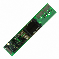
LXMG1627-05-44
Description
MOD INVERTER CCFL DUAL 4W 5V
Manufacturer
Microsemi Analog Mixed Signal Group
Series
PanelMatch™r
Type
Inverters for CCFL and UV Lampsr
Datasheet
1.LXMG1627-05-44.pdf
(6 pages)
Specifications of LXMG1627-05-44
Voltage - Input
5V
Output
440V
Size / Dimension
4.28" L x 0.88" W x 0.40" H (108.7mm x 22.35mm x 10.2mm)
Mounting Type
Chassis Mount
Lead Free Status / RoHS Status
Lead free / RoHS Compliant


Copyright © 2008
Rev. 1.0, 2008-12-04
CN1 (Molex 53261-0871 or equivalent) Mates with 51021-0800 housing, 50079-8100 pins. Mates with LX9501G input cable
assembly
CN2, CN3 for LXMG1627-05-44 (JST SM02(8.0)B-BHS-1-TB (LF)(SN) or Yeon Ho 20015WR-05A00 or equivalent)
Minimum Input for Max. Lamp Current
Maximum Input for Min. Lamp Current
Minimum PWM Input Frequency
SLEEP BAR INPUT
RUN Mode
SLEEP Mode
SET
SET
Input Current
POWER CHARACTERISTICS
Sleep Current
Run Current
Strike (Open Lamps)
Supply Current After Fault Timeout
Efficiency
Input Current
Unless otherwise specified, the following specifications apply over the recommended operating condition and ambient temperature of 0°C
to 60°C,
C
CN1-1
CN1-2
CN1-3
CN1-4
CN1-5
CN1-6
CN1-7
CN1-8
CN2-1
CN3-1
CN2-2
CN3-2
ONN
1,2
1,2
INPUT
Low Threshold
BRITE ≥ 2.5V, SLEEP > 2.0V, V
TM
Parameter
SLEEP
BRITE
SET
SET
GND
P
V
V
V
IN
11861 Western Avenue, Garden Grove, CA. 92841, 714-898-8121, 800-877-6458, Fax: 714-893-2570
LO
IN
HI
1
2
Main Input Power Supply (4.75V ≤ V
Power Supply Return
ON/OFF Control. (0V ≤
Brightness Control (0V to 2.5V). 2.5V insures maximum lamp current.
SET
SET
High voltage connection to high side of lamp. Connect to lamp terminal with shortest lead length. DO
NOT connect to Ground.
Connection to low side of lamp. Connect to lamp terminal with longer lead length.
DO NOT connect to Ground
E L E C T R I C A L C H A R A C T E R I S T I C S ( C O N T I N U E D )
1
2
MSB Connecting this pin to ground decreases the output current (see Table 1)
LSB Connecting this pin to ground decreases the output current (see Table 1)
Symbol
IN
F
V
V
T
F U N C T I O N A L P I N D E S C R I P T I O N
V
V
I
BRT_PWM
I
= 5V
S_DWELL
I
BRT_ADJ
BRT_ADJ
IN(RUN)
IN(MIN)
FAULT
I
I
SLEEP
SLEEP
V
BRT
SET
η
L
except where otherwise noted.
BRITE = 0V
BRITE = 2.5V
I
I
%
SETx = 0V
SET
Fault Timeout
SET
SLEEP ≤ 0.8V
O(LAMP)
O(LAMP)
BRT_PWM
SLEEP
Analog Mixed Signal Group
1
1
= Open, SET
= Open, SET
= Maximum Lamp Current
= Minimum Lamp Current
®
Microsemi
< 50% (Visual Artifact Avoidance)
≤ 0.8 = OFF,
PanelMatch™ RangeMAX™ LXMG1627-05-44
Test Conditions
IN
2
2
≤ 5.25V)
= Ground, V
= Ground, V
5V Dual 4W CCFL Programmable Inverter Module
D
ESCRIPTION
SLEEP ≥
LAMP
LAMP
P
= 530V
= 530V
2.0V = ON)
RODUCTION
RMS
RMS
D
Min
2.1
2.0
1.0
LXMG1627-05-44
8
0
0
ATASHEET
Typ
1460
-420
-18
2.3
1.3
80
-7
0
5
7
Max
2.5
V
0.8
20
2
IN
Units
kHz
Sec
mA
mA
µA
µA
µA
µA
%
V
V
V
V
V
Page 3
Related parts for LXMG1627-05-44
Image
Part Number
Description
Manufacturer
Datasheet
Request
R

Part Number:
Description:
MOD INVERTER CCFL DUAL 6W 12V
Manufacturer:
Microsemi Analog Mixed Signal Group
Datasheet:
Part Number:
Description:
MOD INVERTER CCFL DUAL 4W 5V
Manufacturer:
Microsemi Analog Mixed Signal Group
Datasheet:
Part Number:
Description:
MOD INVERTER CCFL DUAL 4W 12V
Manufacturer:
Microsemi Analog Mixed Signal Group
Datasheet:
Part Number:
Description:
MOD INVERTER CCFL DUAL 4W 12V
Manufacturer:
Microsemi Analog Mixed Signal Group
Datasheet:
Part Number:
Description:
MOD INVERTER CCFL DUAL 4W 5V
Manufacturer:
Microsemi Analog Mixed Signal Group
Datasheet:

Part Number:
Description:
MOD INVERTER CCFL DUAL 6W 12V
Manufacturer:
Microsemi Analog Mixed Signal Group
Datasheet:
Part Number:
Description:
MOD INVERTER CCFL DUAL 4W 5V
Manufacturer:
Microsemi Analog Mixed Signal Group
Datasheet:
Part Number:
Description:
MOD INVERTER CCFL DUAL 6W 5V
Manufacturer:
Microsemi Analog Mixed Signal Group
Datasheet:

Part Number:
Description:
MOD INVERTER CCFL DUAL 4W 12V
Manufacturer:
Microsemi Analog Mixed Signal Group
Datasheet:

Part Number:
Description:
IC USB LINE TERM EMI/ESD SC70-6
Manufacturer:
Microsemi Analog Mixed Signal Group
Datasheet:
Part Number:
Description:
IC USB LINE TERM EMI/ESD SC70-6
Manufacturer:
Microsemi Analog Mixed Signal Group
Datasheet:

Part Number:
Description:
IC TERM SCSI 9LINE MODE 24TSSOP
Manufacturer:
Microsemi Analog Mixed Signal Group
Datasheet:

Part Number:
Description:
IC TERM SCSI 9LINE MODE 28TSSOP
Manufacturer:
Microsemi Analog Mixed Signal Group
Datasheet:

Part Number:
Description:
IC TERM SCSI 9LINE LVD 24TSSOP
Manufacturer:
Microsemi Analog Mixed Signal Group
Datasheet:
Part Number:
Description:
IC TERM SCSI 9LINE MODE 36QSOP
Manufacturer:
Microsemi Analog Mixed Signal Group
Datasheet: