VSML3710-GS08 Vishay, VSML3710-GS08 Datasheet

EMITTER IR PLCC-2 HI PWR 940NM

VSML3710-GS08

Manufacturer Part Number
VSML3710-GS08
Description
EMITTER IR PLCC-2 HI PWR 940NM
Manufacturer
Vishay
Datasheets

Specifications of VSML3710-GS08

Rise Time
800 ns
Radiant Intensity
8 mW/sr
Viewing Angle
120°
Current - Dc Forward (if)
100mA
Radiant Intensity (ie) Min @ If
4mW/sr @ 100mA
Wavelength
950nm
Voltage - Forward (vf) Typ
1.35V
Orientation
Top View
Mounting Type
Surface Mount
Package / Case
PLCC-2
Beam Angle
60 deg
Maximum Forward Current
100 mA
Maximum Power Dissipation
170 mW
Maximum Operating Temperature
+ 85 C
Minimum Operating Temperature
- 40 C
Fall Time
800 ns
Forward Current
100 mA
Forward Voltage
1.35 V
Lens Shape
Circular
Mounting Style
SMD/SMT
Peak Wavelength
940nm
Forward Current If(av)
100mA
Fall Time Tf
800ns
Supply Voltage Range
1.35V To 3V
Lead Free Status / RoHS Status
Lead free / RoHS Compliant
Lead Free Status / RoHS Status
Lead free / RoHS Compliant, Lead free / RoHS Compliant
Other names
751-1257-2

Available stocks

Company
Part Number
Manufacturer
Quantity
Price
Company:
Part Number:
VSML3710-GS08
Quantity:
70 000
High Power Infrared Emitting Diode, 940 nm
RoHS Compliant, Released for Lead (Pb)-free Solder Process
Description
VSML3710 is an infrared emitting diode in GaAlAs on
GaAs technology in miniature PLCC-2 SMD package,
released for Lead (Pb)-free Reflow Soldering.
Features
Order Instructions
Absolute Maximum Ratings
T
Document Number 81300
Rev. 1.2, 25-Jan-07
• High radiant power
• Low forward voltage
• Angle of half intensity: ϕ = ± 60°
• Peak wavelength: λ
• Compatible with automatic placement equipment
• EIA and ICE standard package
• Lead (Pb)-free reflow soldering acc. J-STD-020
• Packed in 8 mm tape
• Suitable for pulse current operation
• Phototransistor with matched package:
• Lead (Pb)-free component in accordance with
VSML3710
VSML3710
Reverse voltage
Forward current
Peak forward current
Surge forward current
Power dissipation
Junction temperature
Operating temperature range
Storage temperature range
Soldering temperature
Thermal resistance
junction / ambient
amb
VEMT3700
RoHS 2002/95/EC and WEEE 2002/96/EC
= 25 °C, unless otherwise specified
Parameter
Part
p
= 940 nm
t
t
acc. figure 11
p
p
/T = 0.5, t
= 100 µs
Test condition
p
= 100 µs
VSML3710-GS08
VSML3710-GS18
e3
Ordering code
Applications
• IR emitter in photointerrupters, sensors and reflec-
• Household appliance
• IR emitter in low space applications
• Tactile keyboards
tive sensors
Symbol
R
T
I
T
I
FSM
T
V
P
amb
FM
T
thJA
I
stg
sd
F
R
V
j
- 40 to +100
- 40 to + 85
MOQ: 7500 pcs, 1500 pcs per reel
MOQ: 8000 pcs, 8000 pcs per reel
Vishay Semiconductors
Value
100
200
170
100
260
400
5
1
VSML3710
Remarks
94 8553
www.vishay.com
K/W
Unit
mW
mA
mA
°C
°C
°C
°C
V
A
1

Related parts for VSML3710-GS08

VSML3710-GS08 Summary of contents

Page 1

... Thermal resistance junction / ambient Document Number 81300 Rev. 1.2, 25-Jan-07 e3 Applications • IR emitter in photointerrupters, sensors and reflec- tive sensors • Household appliance • IR emitter in low space applications • Tactile keyboards Ordering code VSML3710-GS08 VSML3710-GS18 Test condition Symbol 100 µ ...

Page 2

... VSML3710 Vishay Semiconductors 180 160 R = 400 K/W thJA 140 120 100 Ambient Temperature (°C) 20140 amb Figure 1. Power Dissipation Limit vs. Ambient Temperature Basic Characteristics °C, unless otherwise specified amb Parameter Forward voltage I = 100 mA Temp. coefficient Reverse current Junction capacitance MHz Radiant intensity ...

Page 3

... Document Number 81300 Rev. 1.2, 25-Jan-07 100 10 0.05 0.1 100 10 15903 Figure 6. Radiant Intensity vs. Forward Current 1000 100 10 0 8740 Figure 7. Radiant Power vs. Forward Current 1.6 1.2 0.8 0.4 94 7993 Figure 8. Rel. Radiant Intensity/Power vs. Ambient Temperature VSML3710 Vishay Semiconductors Forward Current (mA ...

Page 4

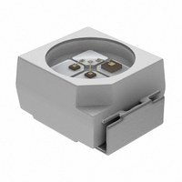
... VSML3710 Vishay Semiconductors 1.25 1.0 0.75 0.5 0. 100 890 940 λ 14291 - Wavelength (nm) Figure 9. Relative Radiant Power vs. Wavelength Package Dimensions 20541_1 www.vishay.com 4 1.0 0.9 0.8 0.7 0.6 990 94 8013 Figure 10. Relative Radiant Intensity vs. Angular Displacement 1.6 (1.9) 0° 10° 20° 30° ...

Page 5

... Adhesive Tape 250 300 200 948626-1 Lead Temperature full line: typical ca. 5 K/s 250 200 1.6 1.4 Figure 14. Tape Dimensions in mm for PLCC-2 VSML3710 Vishay Semiconductors Blister Tape Component Cavity Figure 13. Blister Tape 3.5 2.2 3.1 2.0 5.75 5.25 8.3 3.6 7 ...

Page 6

... VSML3710 Vishay Semiconductors Missing Devices A maximum of 0 the total number of compo- nents per reel may be missing, exclusively missing components at the beginning and at the end of the reel. A maximum of three consecutive components may be missing, provided this gap is followed by six consecutive components. De-reeling direction > ...

Page 7

... Vishay Semiconductor GmbH, P.O.B. 3535, D-74025 Heilbronn, Germany Document Number 81300 Rev. 1.2, 25-Jan-07 and may do so without further notice. VSML3710 Vishay Semiconductors www.vishay.com 7 ...

Page 8

... Vishay disclaims any and all liability arising out of the use or application of any product described herein or of any information provided herein to the maximum extent permitted by law. The product specifications do not expand or otherwise modify Vishay’ ...

Related keywords