HFCT-5914ATLZ Avago Technologies US Inc., HFCT-5914ATLZ Datasheet - Page 2
HFCT-5914ATLZ
Manufacturer Part Number
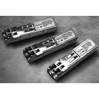
HFCT-5914ATLZ
Description
TXRX SMF LC 1.25GBD 2X10 EXT TMP
Manufacturer
Avago Technologies US Inc.
Datasheet
1.HFCT-5914ATLZ.pdf
(18 pages)
Specifications of HFCT-5914ATLZ
Data Rate
1.25Gbps
Wavelength
1310nm
Applications
Ethernet
Voltage - Supply
3.1 V ~ 3.5 V
Connector Type
LC Duplex
Mounting Type
Through Hole
Supply Voltage
3.3V
Leaded Process Compatible
Yes
Lead Free Status / RoHS Status
Lead free / RoHS Compliant


Functional Description
Receiver Section
Design
The receiver section for the HFCT-5914ATLZ contains an
InGaAs/InP photo detector and a pre-amplifier mounted
in an optical subassembly. This optical subassembly is
coupled to a post-amplifier/decision circuit on a circuit
board. The design of the optical assembly is such that it
provides better than 12 dB Optical Return Loss (ORL).
The post-amplifier is ac coupled to the pre-ampli-
fier as illustrated in Figure 1. The coupling capacitors
are capable of passing the Gigabit Ethernet test pat-
tern at 1.25 Gb/s without any significant distortion or
performance penalty. If a lower signal rate, or a code
which has significantly more low frequency content
is used, sensitivity, jitter and pulse distortion could be
degraded.
Figure 1 also shows a filter function which limits the
bandwidth of the pre-amplifier output signal. The filter
is designed to bandlimit the pre-amplifier output noise
and thus improve the receiver sensitivity.
These components will reduce the sensitivity of the re-
ceiver as the signal bit rate is increased above 1.25 Gb/s.
The device incorporates a photodetector bias circuit.
This output must be connected to V
tored by connecting through a series resistor (see Ap-
plication Section).
Figure 1. Receiver Block Diagram
2
PHOTODETECTOR
BIAS
TRANS-
IMPEDANCE
PRE-
AMPLIFIER
GND
CC
FILTER
and can be moni-
AMPLIFIER
CIRCUIT
SIGNAL
DETECT
Noise Immunity
The receiver includes internal circuit components to
filter power supply noise. However under some condi-
tions of EMI and power supply noise, external power
supply filtering may be necessary (see Application Sec-
tion).
The Signal Detect Circuit
The signal detect circuit works by sensing the peak level
of the received signal and comparing this level to a ref-
erence. The SD output is low voltage TTL.
PECL
OUTPUT
BUFFER
TTL
OUTPUT
BUFFER
DATA OUT
DATA OUT
SD
Related parts for HFCT-5914ATLZ
Image
Part Number
Description
Manufacturer
Datasheet
Request
R

Part Number:
Description:
Fiber Optics, Transceiver Module
Manufacturer:
Avago Technologies US Inc.

Part Number:
Description:
Fiber Optic Transmitters, Receivers, Transceivers SFP OC12 IR Standard Delatch
Manufacturer:
Avago Technologies US Inc.

Part Number:
Description:
Manufacturer:
Avago Technologies
Datasheet:

Part Number:
Description:
155 Mb/s Single Mode Laser Transceiver For Atm, Sonet OC-3/SDH STM-1 (L1.1)
Manufacturer:
Agilent Technologies, Inc.
Datasheet:
Part Number:
Description:
Fiber Optics, Evaluation Kit
Manufacturer:
Avago Technologies US Inc.
Datasheet:
Part Number:
Description:
Fiber Optics, Evaluation Kit
Manufacturer:
Avago Technologies US Inc.
Datasheet:
Part Number:
Description:
Fiber Optics, Evaluation Kit
Manufacturer:
Avago Technologies US Inc.
Datasheet:

Part Number:
Description:
Agilent HFCT-5215B/D 155 Mb/s Single Mode Laser Transceiver
Manufacturer:
Hewlett-Packard
Datasheet:

Part Number:
Description:
Agilent HFCT-5905E MT-RJ Duplex Single Mode Transceiver
Manufacturer:
HP [Agilent(Hewlett-Packard)]
Datasheet:
Part Number:
Description:
LC TRANSCEIVER PORT PLUG
Manufacturer:
Avago Technologies US Inc.

Part Number:
Description:
OPTOCOUPLER GATE DRV 2A 16-SOIC
Manufacturer:
Avago Technologies US Inc.
Datasheet:
Part Number:
Description:
OPTOCOUPLER 2CH 2.5A 16-SOIC
Manufacturer:
Avago Technologies US Inc.
Datasheet:

Part Number:
Description:
OPTOCOUPLER GATE DRV 0.4A 16SOIC
Manufacturer:
Avago Technologies US Inc.
Datasheet:

Part Number:
Description:
OPTOCOUPLER 2.0A 250KHZ 8-DIP
Manufacturer:
Avago Technologies US Inc.
Datasheet:

Part Number:
Description:
OPTOCOUPLER 2.0A 250KHZ GW 8-SMD
Manufacturer:
Avago Technologies US Inc.
Datasheet: