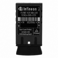
V23826-K305-C373 Infineon Technologies, V23826-K305-C373 Datasheet - Page 3

V23826-K305-C373
Manufacturer Part Number
V23826-K305-C373
Description
TXRX MULT-MODE 850NM 1.3GBIT
Manufacturer
Infineon Technologies
Datasheet
1.V23826-K305-C373.pdf
(9 pages)
Specifications of V23826-K305-C373
Data Rate
1.3Gbps
Wavelength
850nm
Applications
Ethernet
Voltage - Supply
3.1 V ~ 3.5 V
Connector Type
SC
Mounting Type
PCB
Lead Free Status / RoHS Status
Contains lead / RoHS non-compliant
Other names
V23826K305C373IN
TECHNICAL DATA
The electro-optical characteristics described in the following
tables are only valid for use under the recommended operating
conditions.
Recommended Operating Conditions
Notes
1. For V
2. Version C63: Low > 1.2 V; high < V CC – 0.8 V
Transmitter Electro-Optical Characteristics
Notes
1. Into multimode fiber, 62.5 µm or 50 µm diameter.
2. Laser power is shut down if power supply is below V
Fibre Optics
Parameter
Ambient Temperature
Power
Supply
Voltage
Supply
Current
Transmitter
Data Input
High Voltage DC/DC
Data Input
Low Voltage DC/DC
Data Input Differential
Voltage
AC/DC, AC/AC TTL,
AC/AC PECL
Receiver
Input Center
Wavelength
Transmitter
Launched Power
(Average)
Center Wavelength
Spectral Width (RMS)
Relative Intensity Noise
Extinction Ratio (Dynamic) ER
Reset Threshold
Rise/Fall Time, 20%–80% t
Coupled Power Ratio
Power Dissipation
not include the load drive current of the receiver output. Add. max.
45 mA for the three outputs. Load is 50
Version C363: Low > 1.2 V; high < V CC
switched on if power supply is above V
CC
(1)
(2)
–V
(1)
EE
3.3 V
5 V
3.3 V
5 V
(min., max.) 50% duty cycle. The supply current does
(2)
5 V
3.3 V
5V
3.3 V
Symbol
T
V
I
V
V
V
CC
AMB
CC
IH
IL
DIFF
C
Symbol Min.
P
RIN
V
CPR
P
R
–V
–V
C
l
O
TH
Dist
–V
, t
CC
CC
F
EE
Min.
0
3.1
4.75
–1165
–1810
250
770
–9.5
830
9
9
TH
.
to V CC – 2 V.
Typ. Max.
3.3
5
Typ. Max. Units
850
3.5
2.7
0.40 0.62
0.23 0.39
70
3.5
5.25
230
270
–880
–1475
1600
860
TH
–4
860
0.85
–117 dB/Hz
0.26
and
dBm
nm
dB
V
ns
dB
W
Units
°C
V
mA
mV
nm
3
Receiver Electro-Optical Characteristics
Notes
1. Minimum average optical power at which the BER is less than
2. An increase in optical power above the specified level will cause the
3. A decrease in optical power below the specified level will cause the
4. DC/DC, AC/DC for data;
5. Max. output current high: –0.4 mA (drive current)
6. AC/AC for data. Load 50
Receiver
Sensitivity
(Average Power)
Saturation
(Average Power)
Signal Detect
Assert Level
Signal Detect
Deassert Level
Signal Detect
Hysteresis
Signal Detect
Assert Time
Signal Detect
Deassert Time
Output Low Voltage
Output High Voltage
Signal Detect
Output Voltage
AC/AC TTL
Data Output Differential
Voltage
Output Data Rise/Fall
Time, 20%–80%
Return Loss of Receiver A
Power
Dissipation
1x10
Output of multimode fiber 65 µm or 50 µm diameter.
SIGNAL DETECT output to switch from a Low state to a High state.
SIGNAL DETECT to change from a High state to a Low state.
DC/DC, AC/DC, AC/AC PECL for SD
PECL compatible. Load is 50
for Signal Detect. Measured under DC conditions. For dynamic mea-
surements a tolerance of 50 mV should be added. V
T AMB = 25°C.
measurement a tolerance of 50 mV should be added.
V23826-K305-C13/53/63/73, Multimode 850 nm 1.3 Gigabit Ethernet 1x9 Trx
E–12
(6)
or lower. Measured with a 2
(5)
(2)
(3)
(1)
Low
High
5 V
3.3 V
(4)
(4)
low: +2.0 mA (sink current)
Symbol
P
P
P
P
P
P
t
t
V
V
V
V
V
t
P
ASS
DAS
R
to GND or 100
IN
SAT
SDA
SDD
SDA
SDD
OL
OH
SDL
SDH
DIFF
Disr
RL
, t
-V
F
-V
-
into V
CC
CC
Min.
–30
–1950
–1100
2.0
0.5
12
7
CC
–1 NRZ PRBS and ER=9 dB.
–2 V for data, 500 = to V
differential. For dynamic
Typ. Max.
–20
–24
–27
3
0.8
0.63 0.68
0.30 0.42
CC
–17
0
–18
100
350
–1620 mV
–720
0.5
1.23
375
= 3.3 V/5 V.
Units
dBm
dB
V
ps
dB
W
s
EE


