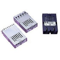
HFBR-5208FMZ Avago Technologies US Inc., HFBR-5208FMZ Datasheet - Page 8

HFBR-5208FMZ
Manufacturer Part Number
HFBR-5208FMZ
Description
TXRX 1X9 622MB/S ST METAL HOUSE
Manufacturer
Avago Technologies US Inc.
Datasheet
1.HFBR-5208Z.pdf
(19 pages)
Specifications of HFBR-5208FMZ
Applications
General Purpose
Data Rate
622Mbps
Wavelength
1300nm
Voltage - Supply
4.75 V ~ 5.25 V
Connector Type
SC
Mounting Type
Through Hole
Data Rate Max
0.622Gbps
Supply Voltage
5V
Wavelength Typ
1300nm
Peak Reflow Compatible (260 C)
Yes
Leaded Process Compatible
Yes
Lead Free Status / RoHS Status
Lead free / RoHS Compliant
An un-shielded option, shown in Figure 7a is available for
the HFBR-5208xxxZ fiber optic transceiver. This unit is
intended for applications where EMI is either not an issue
for the designer, or the unit resides in a highly-shielded
enclosure.
The first shielded option, option EM, is for applications
where the position of the transceiver module will extend
outside the equipment enclosure. The metallized plastic
package and integral external metal shield of the trans-
ceiver helps locally to terminate EM fields to the chassis to
prevent their emissions outside the enclosure. This metal
shield contacts the panel or enclosure on the inside of
the aperture on all but the bottom side of the shield and
provides a good RF connection to the panel. This option
can accommodate various panel or enclosure thicknesses,
i.e. 1.02 mm (.04 in) min to 2.54 mm (0.1 in) max. The refer-
ence plane for this panel thickness variation is from the
front surface of the panel or enclosure. The recommended
length for pro truding the HFBR-5208EMZ transceiver
beyond the front surface of the panel or enclosure is
6.35 mm (0.25 in) . With this option, there is flexibility of
positioning the module to fit the specific need of the en-
closure design. (See Figure 8 for the mechanical drawing
dimensions of this shield.)
The second shielded option, option FM, is for applications
that are designed to have a flush mounting of the module
with respect to the front of the panel or enclosure. The
flush-mount design accommodates a large variety of
panel thickness, i.e. 1.02 mm (.04 in) min to 2.54 mm (0.1
in) max. Note the reference plane for the flush-mount
design is the interior side of the panel or enclosure. The
recommended distance from the centerline of the trans-
ceiver front solder posts to the inside wall of the panel is
13.82 mm (0.544 in) . This option contacts the inside panel
or enclosure wall on all four sides of this metal shield.
(See Figure 10 for the mechanical drawing dimensions
of this shield.)
Both shielded design options connect only to the equip-
ment chassis and not to the signal or logic ground of the
circuit board within the equipment closure. The front
panel aperture dimensions are recommended in Figures
9 and 11. When layout of the printed circuit board is done
to incorporate these metal-shielded transceivers, keep
the area on the printed circuit board directly under the
external metal shield free of any components and circuit
board traces. For additional EMI performance advantage,
use duplex SC fiber-optic connectors that have low metal
content inside the connector. This lowers the ability of the
metal fiber-optic connectors to couple EMI out through
the aperture of the panel or enclosure.
8
Recommended Solder and Wash Process
The HFBR-5208xxxZ is compatible with industry-standard
wave or hand solder processes.
HFBR-5000 Process Plug
The HFBR-5208xxxZ transceiver is supplied with a process
plug, the HFBR-5000, for protection of the optical ports
with the Duplex SC connector receptacle. This process
plug prevents contamination during wave solder and
aqueous rinse as well as during handling, shipping or
storage. It is made of high-temperature, molded, sealing
material that will withstand +85°C and a rinse pressure
of 110 lb/in
Recommended Solder Fluxes and Cleaning/Degreasing
Chemicals
Solder fluxes used with the HFBR-5208xxxZ fiber-optic
transceiver should be water-soluble, organic solder fluxes.
Some recommended solder fluxes are Lonco 3355-11 from
London Chemical West, Inc. of Burbank, CA, and 100 Flux
from Alpha-metals of Jersey City, NJ or equivalent fluxes
from other companies.
Recommended cleaning and degreasing chemicals for
the HFBR-5208xxxZ are alcohols (methyl, isopropyl, iso-
butyl), aliphatics (hexane, heptane) and other chemicals,
such as soap solution or naphtha. Do not use partially
halogenated hydrocarbons for cleaning/degreasing.
Examples of chemicals to avoid are 1,1.1 trichloroethane,
ketones (such as MEK), acetone, chloroform, ethyl acetate,
methylene dichloride, phenol, methylene chloride or N
methylpyrolldone.
Regulatory Compliance
These transceiver products are intended to enable com-
mercial system designers to develop equipment that com-
plies with the various regulations governing certification
of Information Technology Equipment. See the Regulatory
Compliance Table for details. Additional information is
available from your Avago sales representative.
2
.


