HFBR-57E0PZ Avago Technologies US Inc., HFBR-57E0PZ Datasheet - Page 6
HFBR-57E0PZ
Manufacturer Part Number
HFBR-57E0PZ
Description
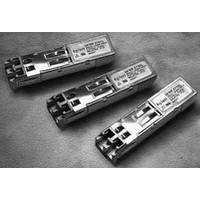
TXRX MM SFP LC CONN BAIL DELATCH
Manufacturer
Avago Technologies US Inc.
Series
-r
Specifications of HFBR-57E0PZ
Applications
Ethernet
Mounting Type
SFP
Voltage - Supply
2.97 V ~ 3.63 V
Connector Type
LC Duplex
Wavelength
1300nm
Data Rate
155MBd
Supply Voltage
3.3V
Wavelength Typ
1300nm
Leaded Process Compatible
Yes
Optical Fiber Type
TX/RX
Optical Rise Time
3/2.2ns
Optical Fall Time
3/2.2ns
Jitter
0.1/0.14ns
Operating Temperature Classification
Commercial
Peak Wavelength
1308/1380nm
Package Type
SFP
Operating Supply Voltage (min)
2.97V
Operating Supply Voltage (typ)
3.3V
Operating Supply Voltage (max)
3.63V
Output Current
50mA
Operating Temp Range
0C to 70C
Mounting
Snap Fit To Panel
Pin Count
20
Product
Transceiver
Maximum Rise Time
3 ns, 2.2 ns
Maximum Fall Time
3 ns, 2.2 ns
Pulse Width Distortion
0.1 ns, 0.14 ns
Maximum Output Current
50 mA
Operating Supply Voltage
2.97 V to 3.63 V
Maximum Operating Temperature
+ 70 C
Minimum Operating Temperature
0 C
Package / Case
SFP-20
Function
SFF Pluggable Transceivers with LC connector for ATM, FDDI, Fast Ethernet and SONET OC-3/SDH STM-1
Lead Free Status / RoHS Status
Lead free / RoHS Compliant
For Use With
Multimode Glass
Lead Free Status / RoHS Status
Lead free / RoHS Compliant, Lead free / RoHS Compliant
Available stocks
Company
Part Number
Manufacturer
Quantity
Price
Company:

Part Number:
HFBR-57E0PZ
Manufacturer:
Avago Technologies
Quantity:
135


Table 2. Pin Description
Notes:
1.
2.
3.
4.
5.
6.
6
Pin
1
6
10
11
12
13
14
15
16
17
18
19
2
3
4
5
7
8
9
20
Pin 2 connected to internal ground.
Mod-Def 0, 1, 2. are the module definition pins. They should be pulled up with a 4.7 K - 10 KΩ resistor on the host board to a supply
less than V
Mod-Def 0 is grounded by the module to indicate that the module is present.
Mod-Def 1 is clock line of two wire serial interface for optional serial ID.
Mod-Def 2 is data line of two wire serial interface for optional serial ID.
LOS (Loss of Signal) is an open collector/drain output which should be pulled up externally with a 4.7 - 10 KΩ resistor on the host
board to a supply < V
sensitivity (as defined by the standard in use). Low indicates normal operation. In the low state, the output will be pulled to <0.8 V.
RD-/+: These are the differential receiver outputs. They are ac coupled 100 Ω differential lines which should be terminated with
100 Ω differential at the SERDES. The ac coupling is done inside the module and is thus not required on the host board. The voltage
swing on these lines will be between 400 and 2000 mV differential (200 - 1000 mV single ended) when properly terminated.
V
maximum supply current is 230 mA and the associated in-rush current will typically be no more than 30 mA above steady state after
500 nanoseconds.
TD-/+: These are the differential transmitter inputs. They are ac coupled differential lines with 100 Ω differential termination
inside the module. The ac coupling is done inside the module and is thus not required on the host board. The inputs will accept
differential swings of 400 - 2000 mV (200 - 1000 mV single ended), though it is recommended that values between 400 and 1200
mV differential (200 - 600 mV single ended) be used for best EMI performance. These levels are compatible with CML and LVPECL
voltage swings.
CC
R and V
Name
NC
MOD-DEF2
MOD-DEF1
MOD-DEF0
NC
LOS
RD-
RD+
V
Tx Disable
V
V
V
V
V
V
V
TD+
TD-
V
EE
EE
EE
EE
EE
CC
CC
EE
EE
T
R
R
R
R
T
T
R
T
CC
CC
T +0.3 V or V
T are the receiver and transmitter power supplies. They are defined as 2.97 - 3.63 V at the SFP connector pin. The
CC
T, R +0.3 V. When high, this output indicates the received optical power is below the worst case receiver
CC
Function/Description
Transmitter Ground
NC
Module Definition 2 - Two Wire Serial ID Interface
Module Definition 1 - Two Wire Serial ID Interface
Module Definition 0 - grounded in module
NC
Loss of Signal - high indicates loss of signal
Receiver Ground
Receiver Ground
Receiver Ground
Inverse Received Data Out
Received Data Out
Receiver Ground
Receiver Power -3.3 V ± 10%
Transmitter Power -3.3 V ± 10%
Transmitter Ground
Transmitter Data In
Inverse Transmitter Data In
Transmitter Ground
Transmitter Disable- Module disables on high or open
R +0.3 V.
MSA Notes
1
2
2
2
3
5
5
6
6
4
4
Related parts for HFBR-57E0PZ
Image
Part Number
Description
Manufacturer
Datasheet
Request
R

Part Number:
Description:
XMITTER OPTICAL 2MBD SERCOS
Manufacturer:
Avago Technologies US Inc.
Datasheet:
Part Number:
Description:
Fiber Optic Transmitters, Receivers, Transceivers SERCOS TRANSMITTER
Manufacturer:
Avago Technologies US Inc.

Part Number:
Description:
RECEIVER FIBER OPTIC 600NM 40KBD
Manufacturer:
Avago Technologies US Inc.
Datasheet:

Part Number:
Description:
XMITTER FIBER OPTIC 600NM 5MBD
Manufacturer:
Avago Technologies US Inc.
Datasheet:

Part Number:
Description:
XMITTER FIBER OPTIC 600NM 40KBD
Manufacturer:
Avago Technologies US Inc.
Datasheet:

Part Number:
Description:
XMITTER VERSATILE LINK HORZ
Manufacturer:
Avago Technologies US Inc.
Datasheet:

Part Number:
Description:
XMITTER OPT HI PERFORMANCE VERT
Manufacturer:
Avago Technologies US Inc.
Datasheet:

Part Number:
Description:
TXRX FIBER OPTIC 650NM 10MBAUD
Manufacturer:
Avago Technologies US Inc.
Datasheet:
Part Number:
Description:
TXRX FIBER OPTIC 650NM 10MBAUD
Manufacturer:
Avago Technologies US Inc.
Datasheet:

Part Number:
Description:
FIBER OPTIC TRANSMITTER 660NM
Manufacturer:
Avago Technologies US Inc.
Datasheet:

Part Number:
Description:
KIT EVAL FIBER OPTIC 5MBD
Manufacturer:
Avago Technologies US Inc.
Datasheet:
Part Number:
Description:
KIT EVAL FIBER OPTICS 32MBD
Manufacturer:
Avago Technologies US Inc.
Datasheet:

Part Number:
Description:
KIT EVAL FIBER OPTIC 5MBD
Manufacturer:
Avago Technologies US Inc.
Datasheet:

Part Number:
Description:
125MBd 1300nm FiberOptic Eval Kit
Manufacturer:
Avago Technologies US Inc.
Datasheet:

Part Number:
Description:
DC-5MBd 820nm FiberOptic EvalKit
Manufacturer:
Avago Technologies US Inc.
Datasheet: