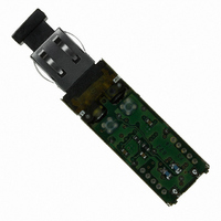
HFBR-5912EZ Avago Technologies US Inc., HFBR-5912EZ Datasheet - Page 9

HFBR-5912EZ
Manufacturer Part Number
HFBR-5912EZ
Description
TXRX OPTICAL 850NM VCSEL MT-RJ
Manufacturer
Avago Technologies US Inc.
Datasheet
1.HFBR-5912EZ.pdf
(13 pages)
Specifications of HFBR-5912EZ
Wavelength
850nm
Voltage - Supply
3.3V
Connector Type
MTRJ
Mounting Type
Through Hole
Function
MMF Transceiver for Gigabit Ethernet, RoHs
Product
Transceiver
Data Rate
1.25 GBd
Maximum Rise Time
0.26 ns/0.4 ns
Maximum Fall Time
0.26 ns/0.4 ns
Pulse Width Distortion
0.227 ns (Max)
Maximum Output Current
30 mA
Operating Supply Voltage
3.14 V to 3.47 V
Maximum Operating Temperature
+ 70 C
Minimum Operating Temperature
0 C
Package / Case
DIP With Connector
Lead Free Status / RoHS Status
Lead free / RoHS Compliant
Applications
-
Lead Free Status / Rohs Status
Lead free / RoHS Compliant
Other names
516-2085
Available stocks
Company
Part Number
Manufacturer
Quantity
Price
Company:
Part Number:
HFBR-5912EZ
Manufacturer:
Avago Technologies US Inc.
Quantity:
135
Company:
Part Number:
HFBR-5912EZ
Manufacturer:
AGILENT
Quantity:
5
Figure 2. Pin Out
Table 1. Pin Out Table
Four Package
Grounding Tabs
9
Two Mounting Studs The mounting studs are provided for transceiver mechanical attachment to the circuit board, they
Pin
10
2
3
4
5
6
7
8
9
1
Symbol
V
V
TDis
RD+
TD+
V
V
RD-
TD-
SD
EER
EET
CCR
CCT
1
1
Receiver Signal Ground
Directly connect this pin to receiver signal ground plane.
Receiver Power Supply
Normal operation: Logic “1” Output
Fault Condition: Logic “0” Output
Received Data Out Bar
No internal terminations provided.
Received Data Out
No internal terminations provided.
Normal Operation: Logic "0" - Laser On or Open Circuit
may also provide an optional connection of the transceiver to the equipment chassis ground.
Note :-
Connect to signal ground.
Signal Detect
(See TD+ pin for terminaton details)
Transmitter Power Supply
Transmitter Signal Ground
Transmitter Disable:
Transmit Disabled: Logic "1" - Laser Off
Transmitter Data In
An internal 50R termination consisting of 100R across TD+ and TD- will be provided
Transmitter Data In Bar
RECEIVER SIGNAL GROUND
RECEIVER POWER SUPPLY
RECEIVER DATA OUT BAR
RECEIVER DATA OUT
The holes in the circuit board must be tied to chassis ground.
Grounding Tabs
SIGNAL DETECT
Package
RX
1
2
3
4
5
View
Top
Functional Description
10
TX
9
8
7
6
TRANSMITTER DATA IN BAR
TRANSMITTER DATA IN
TRANSMITTER DISABLE
TRANSMITTER SIGNAL GROUND
TRANSMITTER POWER SUPPLY
Mounting Studs/
Solder Posts


