TRX10GDP0301 FCI, TRX10GDP0301 Datasheet
TRX10GDP0301
Specifications of TRX10GDP0301


Related parts for TRX10GDP0301


TRX10GDP0301 Summary of contents
Page 1
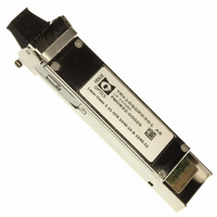
XFP Transceiver 1310 nm (TRX10GDP0x01) Features Fully compliant to XFP MSA Rev. 4.5 Multi-Protocol in the range of 9.9….10.7Gb/s for SONET/SDH, Ethernet and Fibre Channel Applications Compatible with 10.7Gbit/s and 11.3Gbit/s operation for FEC functionality Transmission distance up to ...
Page 2
Electrical Characteristics Absolute Maximum Ratings Rating Storage Ambient Temperature Range Powered Case Temperature Range Operating Relative Humidity Supply Voltage Range @ 5.0V Supply Voltage Range @ 3.3V Open Drain VCC Level Static Discharge Voltage on XFI High Speed Pins Static ...
Page 3
High Speed Line Output - DC Characteristics Parameter Single Ended Output Impedance Differential Output Impedance High Speed Line Output - AC Characteristics Parameter Differential Output Amplitude Output Common Mode Transition Time Low to High Transition Time High to Low Differential ...
Page 4
TRX10GDPxx01 Copyright © 2008 MergeOptics GmbH, MergeOptics GmbH reserves the right to make changes in design, specifications and other information at any time without prior notice. Information in this data sheet is believed to be reliable. However, no responsibility is ...
Page 5
Optical Characteristics General Parameters Parameter Operating Range Nominal Signalling Speed Speed Variation from Nominal Speed Optical Transmitter Parameter Nominal Wavelength Spectral Width Side Mode Suppression Ratio Optical Output Power Extinction Ratio Extinction Ratio Optical Modulation Amplitude Laser Turn OFF Time ...
Page 6
Hostboard Connector Pinout TRX10GDPxx01 Copyright © 2008 MergeOptics GmbH, MergeOptics GmbH reserves the right to make changes in design, specifications and other information at any time without prior notice. Information in this data sheet is believed to be reliable. However, ...
Page 7
Electrical Pin Definition PIN Logic Symbol Name / Description 1 GND Module Ground 2 VEE5 Optional -5.2V Power Supply Mode De-select; When held low allows module to respond to 2-wire serial 3 LVTTL-I Mod_DeSel interface commands Interrupt (inverted); Indicates presence ...
Page 8
Management Interface Memory specification Parameter Complete Single or Sequential Write Endurance (Write Cycles) Single Byte Writable Memory Blocks Byte Address Volatile or NV 110 V 118 V 127 V Multiple Byte Writab le Memory Blocks Byte Address Volatile or ...
Page 9
Lower Memory map Byte Default value (hex) address 2-57 See table below 58-59 00 60-69 00 70-71 00 72-75 00 76-79 00 80-95 - 96-109 - 110-111 - 112-117 00 118 - 119-122 - 123-126 - ...
Page 10
F4 AUX 2 Low Warning 56-57 Flags and Interrupt Control Byte Bit address 80 7 Latched high Temperature alarm 80 6 Latched low Temperature alarm 80 5 Reserved 80 4 Reserved 80 3 Latched high TX Bias alarm 80 ...
Page 11
Reserved 85 0 Reserved 86 7 VCC5 High Alarm Flag 86 6 VCC5 Low Alarm Flag 86 5 VCC3 High Alarm Flag 86 4 VCC3 Low Alarm Flag 86 3 VCC2 High Alarm Flag 86 2 VCC2 Low ...
Page 12
Masking bit for low AUX2 monitor warning 91 1 Reserved 91 0 Reserved 92 7 Masking bit for TX_NR Status 92 6 Masking bit for Laser Fault condition 92 5 Masking bit for TX CDR Loss of Lock ...
Page 13
General Control/Status bits Byte Bit address 110 7 TX Disable State Digital state of the TX Disable Input Pin. 110 6 Soft TX Disable Optional read/write bit that allows software disable of laser. Writing '1' disables laser. This bit is ...
Page 14
Memory map table 01h Byte Default value (hex) address 128 06 129 50 130 07 131-138 40, 40, 00, 00, 00, 00, 80, 00 139 F0 140 63 141 6B 142 0A 143 00 144 00 145 00 146 00 ...
Page 15
Power Supply Power supply current requirements and max power dissipation Byte Default value (hex) address 192 7D 193 96 194 16 195 00 Memory map table 02h Byte Default value (hex) address 128 - 255 00 TRX10GDPxx01 Copyright © 2008 ...
Page 16
Electro Static Discharge (ESD) The maximum electrostatic charge based on a human body model and the conditions as outlined below is: Parameter On XFI High Speed Pins On XFI Pins excluding High Speed Pins On XFP Module On XFP Module ...
Page 17
Eye Safety This laser based multimode transceiver is a Class 1 product. It complies with IEC 60825-1: 2007 and FDA performance standards for laser products (21 CFR 1040.10 and 1040.11) except for deviations pursuant to Laser Notice 50, dated June ...
Page 18
Ordering Information TRX10G Optical Interface DP DFB Laser Standard IEEE802.3ae, 10GBASE-LR 03 10GFC, 1200-SM-LL-L TELCORDIA GR253 OC192 SR-I 05 ITU-T G.691 I-64.1r/I-64.1 For more information on our products, please email us at www.mergeoptics.com TRX10GDPxx01 Copyright © 2008 MergeOptics GmbH, MergeOptics ...