HFBR-2412TZ Avago Technologies US Inc., HFBR-2412TZ Datasheet - Page 22
HFBR-2412TZ
Manufacturer Part Number
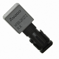
HFBR-2412TZ
Description
RECEIVER FIBER OPTIC 5MBD TTL ST
Manufacturer
Avago Technologies US Inc.
Specifications of HFBR-2412TZ
Data Rate
5MBd
Voltage - Supply
4.75 V ~ 5.25 V
Power - Minimum Receivable
-25.4dBm
Current - Supply
10mA
Function
Optical Receivers for Industrial Application, TTL Output, Threaded ST Port
Product
Receiver
Wavelength
820 nm
Diode Capacitance
55 pF
Maximum Output Current
25 mA
Operating Supply Voltage
4.75 V to 5.25 V
Maximum Operating Temperature
+ 85 C
Minimum Operating Temperature
- 40 C
Optical Fiber Type
RX
Data Transfer Rate
5MBd
Operating Temperature Classification
Industrial
Operating Supply Voltage (min)
4.75V
Operating Supply Voltage (typ)
5V
Operating Supply Voltage (max)
5.25V
Output Current
25mA
Operating Temp Range
-40C to 85C
Mounting
Through Hole
Pin Count
8
Lead Free Status / RoHS Status
Lead free / RoHS Compliant
Applications
-
Lead Free Status / Rohs Status
Compliant
For Use With
Multimode Glass, Hard Clad Silica
Lead Free Status / RoHS Status
Lead free / RoHS Compliant, Lead free / RoHS Compliant
Other names
516-2055
Available stocks
Company
Part Number
Manufacturer
Quantity
Price
Company:

Part Number:
HFBR-2412TZ
Manufacturer:
AVAGO
Quantity:
340


HFBR-24x6Z Low-Cost 125 MHz Receiver
Description
The HFBR-24x6Z fiber optic receiver is designed to oper-
ate with the Avago Technologies HFBR-14xxZ fiber optic
transmitters and 50/ 125 μm, 62.5/125 μm, 100/140 μm
and 200 μm HCS® fiber optic cable. Consistent coupling
into the receiver is assured by the lensed optical system
(Figure 1). Response does not vary with fiber size for core
diameters of 100 μm or less.
The receiver output is an analog signal which allows
follow-on circuitry to be optimized for a variety of dis-
tance/data rate requirements. Low-cost external compo-
nents can be used to convert the analog output to logic
compatible signal levels for various data formats and
data rates up to 175 MBd. This distance/data rate trade-
off results in increased optical power budget at lower
data rates which can be used for additional distance or
splices.
The HFBR-24x6Z receiver contains a PIN photodiode
and low noise transimpedance preamplifier integrated
circuit. The HFBR-24x6Z receives an optical signal and
converts it to an analog voltage. The output is a buffered
Figure 13. Simplified Schematic Diagram.
22
CAUTION: The small junction sizes inherent to the design of these components increase the components’ susceptibility to damage
from electrostatic discharge (ESD). It is advised that normal static precautions be taken in handling and assembly of these compo-
nents to prevent damage and/or degradation which may be induced by ESD.
BIAS & FILTER
CIRCUITS
mA
5.0
300 pF
V OUT
V CC
V EE
3, 7
6
2
POSITIVE
SUPPLY
ANALOG
SIGNAL
NEGATIVE
SUPPLY
emitter follower. Because the signal amplitude from the
HFBR-24x6Z receiver is much larger than from a simple
PIN photodiode, it is less susceptible to EMI, especially
at high signaling rates. For very noisy environments,
the conductive or metal port option is recommended.
A receiver dynamic range of 23 dB over temperature is
achievable (assuming 10-9 BER).
The frequency response is typically dc to 125 MHz.
Although the HFBR-24x6Z is an analog receiver, it is
compatible with digital systems. Please refer to Applica-
tion Bulletin 78 for simple and inexpensive circuits that
operate at 155 MBd or higher.
The recommended ac coupled receiver circuit is shown
in Figure 14. It is essential that a 10 ohm resistor be con-
nected between pin 6 and the power supply, and a 0.1
mF ceramic bypass capacitor be connected between the
power supply and ground. In addition, pin 6 should be
filtered to protect the receiver from noisy host systems.
Refer to AN 1038, 1065, or AB 78 for details.
Housed Product
BOTTOM VIEW
PIN
1
3
4
5
7
8
2
6
1
2
1
1
2
1
FUNCTION
NC
SIGNAL
V
NC
NC
V
V
NC
EE
CC
EE
4 5
3
2
1
6
7
8
NOTES:
1. PINS 1, 4, 5 AND 8 ARE ISOLATED
2. PINS 3 AND 7 ARE ELECTRICALLY
PIN 1 INDICATOR
2
3 & 7
6
FROM THE INTERNAL CIRCUITRY,
BUT ARE CONNECTED TO EACH OTHER.
CONNECTED TO THE HEADER.
V
ANALOG SIGNAL
V
cc
EE
Related parts for HFBR-2412TZ
Image
Part Number
Description
Manufacturer
Datasheet
Request
R

Part Number:
Description:
FIBER OPTIC CONN LATCH GRY SIMPL
Manufacturer:
Avago Technologies US Inc.
Datasheet:

Part Number:
Description:
FIBER OPTIC CONN LATCH BLU SIMPL
Manufacturer:
Avago Technologies US Inc.
Datasheet:

Part Number:
Description:
FIBER OPTIC CRIMPLESS CONN GRAY
Manufacturer:
Avago Technologies US Inc.
Datasheet:

Part Number:
Description:
FIBER OPTIC CONN BLUE SIMPLEX
Manufacturer:
Avago Technologies US Inc.
Datasheet:

Part Number:
Description:
FIBER OPTIC CONN LATCH DUPLEX
Manufacturer:
Avago Technologies US Inc.
Datasheet:

Part Number:
Description:
FIBER OPTIC CONN DUPLEX
Manufacturer:
Avago Technologies US Inc.
Datasheet:

Part Number:
Description:
FIBER OPTIC CONN GRAY SIMPLEX
Manufacturer:
Avago Technologies US Inc.
Datasheet:

Part Number:
Description:
FIBER OPTIC CBL DUPLEX 1=100M
Manufacturer:
Avago Technologies US Inc.
Datasheet:

Part Number:
Description:
FIBER OPTIC CBL DUPLEX 1=500M
Manufacturer:
Avago Technologies US Inc.
Datasheet:

Part Number:
Description:
FIBER OPTIC CBL CONN DUPLEX 5M
Manufacturer:
Avago Technologies US Inc.
Datasheet:

Part Number:
Description:
OPTOCOUPLER GATE DRV 2A 16-SOIC
Manufacturer:
Avago Technologies US Inc.
Datasheet:
Part Number:
Description:
OPTOCOUPLER 2CH 2.5A 16-SOIC
Manufacturer:
Avago Technologies US Inc.
Datasheet:

Part Number:
Description:
OPTOCOUPLER GATE DRV 0.4A 16SOIC
Manufacturer:
Avago Technologies US Inc.
Datasheet:

Part Number:
Description:
OPTOCOUPLER 2.0A 250KHZ 8-DIP
Manufacturer:
Avago Technologies US Inc.
Datasheet:

Part Number:
Description:
OPTOCOUPLER 2.0A 250KHZ GW 8-SMD
Manufacturer:
Avago Technologies US Inc.
Datasheet: