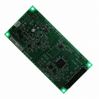
GU128X64-800B Noritake Company Inc, GU128X64-800B Datasheet - Page 2

GU128X64-800B
Manufacturer Part Number
GU128X64-800B
Description
MODULE VF GRAPHIC DISPLAY 128X64
Manufacturer
Noritake Company Inc
Series
800r
Datasheet
1.GU128X64-800B.pdf
(22 pages)
Specifications of GU128X64-800B
Viewing Area
83.10mm L x 41.50mm W
Display Format
21 x 8
Display Type
Graphic
Format
5 x 7 Dots
Voltage - Supply
5V
Number Of Dots
128 x 64
Operating Temperature
-40°C ~ 80°C
Lead Free Status / RoHS Status
Lead free / RoHS Compliant
Interface
-
Outline L X W X H
-
Character Size
-
Other names
286-1060
1. General Description ................................................................................................................................................2
2. Absolute Maximum Ratings ...................................................................................................................................2
3. Electrical Characteristics .......................................................................................................................................2
4. Optical Specifications.............................................................................................................................................2
5. Environmental Specifications ................................................................................................................................2
6. Description of Bus and Signals .............................................................................................................................3
7. Block Diagram .........................................................................................................................................................3
8. Display Screen and Initialize Set ...........................................................................................................................4
9. Function ...................................................................................................................................................................7
10. Interface ................................................................................................................................................................15
11. Jumper ..................................................................................................................................................................18
12. Pin Assignment (See connector diagrams below) ..............................................................................................19
13. Outline Dimension ..............................................................................................................................................20
6.1 Parallel Interface ...........................................................................................................................................3
6.2 Serial Interface ..............................................................................................................................................3
8.1 Graphic Display (GRAM) ...............................................................................................................................5
9.1 Commands ....................................................................................................................................................7
9.2 Display On/Off (C/D= "1") ..............................................................................................................................8
9.3 Brightness Set (C/D= "1") ..............................................................................................................................8
9.4 Display Clear (C/D= "1") This command clears the GRAM. .........................................................................9
9.5 Display Area Set (C/D="1", only used for Initialize Set) ...............................................................................10
9.6 GRAM Data Write position Address Set (Graphic Display) (C/D="1").......................................................... 11
9.8 Address Mode Set(C/D="1") ..................................................................................................................12
9.9 Address Read (C/D ="1") .......................................................................................................................12
9.10 Data Write to Graphic Display(GRAM) (C/D="0") ......................................................................................13
9.11 Default Status at Reset ..............................................................................................................................14
9.12 FRP (Frame Pulse)..................................................................................................................................14
10.1 Parallel Interface (Parallel #1) ...................................................................................................................15
10.2 Parallel Interface(Parallel #2) ....................................................................................................................16
10.3 Serial Interface ..........................................................................................................................................17
11.1 Jumper Position .........................................................................................................................................18
11.2 Jumper Setting (Must be done when power is OFF)................................................................................18
12.1 Signal Connection .....................................................................................................................................19
12.2 Connectors ...............................................................................................................................................19
9.7 GRAM Display Start Position Address Set (C/D="1") ................................................................................. 11
9.6.1 GRAM Data Write Position X Address Set ............................................................................................ 11
9.6.2 GRAM Data Write Position Y Address Set ............................................................................................ 11
9.7.1 Horizontal Shift...................................................................................................................................... 11
9.7.2 Vertical Shift .......................................................................................................................................... 11
10.1.1 Command Write operation ..................................................................................................................15
10.1.2 Command Read operation .................................................................................................................15
10.1.3 Data Write operation ...........................................................................................................................15
10.2.1 Command Write operation ..................................................................................................................16
10.2.2 Command Read operation ..................................................................................................................16
10.2.3 Data Write operation ...........................................................................................................................16
10.3.1 Timing .................................................................................................................................................17
Table of Contents
GU128X64-800B
1


