HDSP-2531 Avago Technologies US Inc., HDSP-2531 Datasheet - Page 14
HDSP-2531
Manufacturer Part Number
HDSP-2531
Description
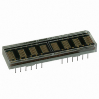
LED DISPLAY 5X7 8CHAR 5MM YLW
Manufacturer
Avago Technologies US Inc.
Series
HDSP-253xr
Datasheet
1.HDSP-2533.pdf
(15 pages)
Specifications of HDSP-2531
Display Type
Alphanumeric
Common Pin
*
Package / Case
28-DIP
Color
Yellow
Size / Dimension
1.69" x .45" (42.9mm x 11.4mm)
Number Of Digits/alpha
8
Digit/alpha Size
0.20" (5mm)
Number Of Digits
8
Character Size
2.54 mm x 4.57 mm
Illumination Color
Yellow
Wavelength
585 nm
Operating Voltage
5 V
Operating Current
370 mA
Maximum Operating Temperature
+ 85 C
Minimum Operating Temperature
- 40 C
Luminous Intensity
7.5 ucd
Viewing Area (w X H)
40.06 mm x 4.57 mm
Lead Free Status / RoHS Status
Lead free / RoHS Compliant
Lead Free Status / RoHS Status
Lead free / RoHS Compliant, Lead free / RoHS Compliant
Other names
516-1168-5
Available stocks
Company
Part Number
Manufacturer
Quantity
Price
Company:

Part Number:
HDSP-2531
Manufacturer:
NICHIA
Quantity:
30 000
Company:
Part Number:
HDSP-2531
Manufacturer:
Avago Technologies US Inc.
Quantity:
135
Part Number:
HDSP-2531
Manufacturer:
HP
Quantity:
20 000


Table 3 shows the calculated maximum allowable ambient
temperature for several different sets of operating condi-
tions. The worst case alphanumeric characters (#,@,B)
have 20 pixels. Displaying eight 20-pixel characters will
not occur in normal operation. Thus, using eight 20-pixel
characters to calculate power dissipation will over estimate
the power and the IC junction temperature. The average
number of pixels per character, supply voltage, brightness
level, and number of characters are needed to calculate
the power dissipated by the IC. The ambient temperature,
power dissipated by the IC, and the thermal resistance
are then used to calculate IC junction temperature. The
typical alphanumeric character is 15 pixels. For conditions
not listed in Table 3, you can calculate the power dissipat-
ed by the IC and use Figure 10 to determine the maximum
ambient temperature.
Table 3. Maximum Allowable Ambient Temperature for Various Operating Conditions
AlGaAs Red
Character
# (20 dots)
# (20 dots)
# (20 dots)
# (20 dots)
# (20 dots)
# (20 dots)
# (20 dots)
# (20 dots)
V (12 dots)
Table 4. Maximum Allowable Ambient Temperature for Various Operating Conditions (cont’ d .)
All Colors Except AlGaAs Red
Character
# (20 dots)
# (20 dots)
# (20 dots)
# (20 dots)
# (20 dots)
# (20 dots)
V (12 dots)
The actual IC temperature is easy to measure. Pin 17 is thermally and electrically connected to the IC substrate. The thermal resistance from pin 17 to
the IC is 16°C/W. The procedure to measure the IC junction temperature is as follows:
1. Measure V
2. Measure the temperature of pin 17 after 45 minutes. Use an electrically isolated thermal couple probe.
3. T
14
J
(IC) = T
pin
DD
+ V
and I
DD
x I
DD
Number of
Characters
8
8
8
7
6
8
8
8
8
Number of
Characters
8
8
8
7
6
8
8
DD
for the display. Measure V
x 16°C/W.
Brightness
Level
100%
100%
100%
100%
100%
80%
80%
53%
100%
Brightness
Level
100%
100%
100%
100%
100%
80%
100%
DD
between pins 15 and 16. Measure the current entering pin 15.
V
V
5.5
5.25
5.0
5.5
5.5
5.5
5.25
5.5
5.5
V
V
5.5
5.25
5.0
5.5
5.5
5.5
5.5
DD
DD
Figure 10. Maximum allowable power dissipation vs. ambient temperature.
T
J
MAX = 150°C or 120°C.
I
mA
408
387
366
357
306
327
310
216
228
I
mA
373
354
335
326
280
298
207
DD
DD
2.3
2.2
2.1
2.0
1.9
1.8
1.7
1.6
1.5
50
ALL OTHER COLORS
55 60
T
A
AlGaAs
– AMBIENT TEMPERATURE – C
65
P
W
2.2
2.0
1.8
2.0
1.7
1.8
1.6
1.2
1.3
P
W
2.0
1.9
1.67
1.8
1.5
1.6
1.1
70
D
D
Rθ
75
J-A
= 39C/W
80
85
Rq
°C/W
39
39
39
39
39
39
39
39
39
Rq
°C/W
39
39
39
39
39
39
39
J-A
J-A
90
T
°C
64
72
80
72
84
80
85
85
85
T
°C
72
77
85
80
85
85
85
A
A
MAX
MAX
Related parts for HDSP-2531
Image
Part Number
Description
Manufacturer
Datasheet
Request
R

Part Number:
Description:
LED 7-SEG 7.6MM CC HE RED RHD
Manufacturer:
Avago Technologies US Inc.
Datasheet:

Part Number:
Description:
LED 7-SEG 7.6MM CA HE RED RHD
Manufacturer:
Avago Technologies US Inc.
Datasheet:

Part Number:
Description:
Seven-Segment Numeric LED Display,2-CHARACTER,Red,DIP
Manufacturer:
Avago Technologies US Inc.
Datasheet:

Part Number:
Description:
Seven-Segment Numeric LED Display,2-CHARACTER,Green,DIP
Manufacturer:
Avago Technologies US Inc.
Datasheet:
Part Number:
Description:
Seven-Segment Numeric LED Display,2-CHARACTER,Green,DIP
Manufacturer:
Avago Technologies US Inc.
Datasheet:
Part Number:
Description:
Seven-Segment Numeric LED Display,2-CHARACTER,Red,DIP
Manufacturer:
Avago Technologies US Inc.
Datasheet:
Part Number:
Description:
Seven-Segment Numeric LED Display,2-CHARACTER,Green,DIP
Manufacturer:
Avago Technologies US Inc.
Datasheet:

Part Number:
Description:
Seven-Segment Numeric LED Display,2-CHARACTER,Orange-Red,DIP
Manufacturer:
Avago Technologies US Inc.
Datasheet:

Part Number:
Description:
LED 7-SEG 14.2MM 2DIG CC HER RHD
Manufacturer:
Avago Technologies US Inc.
Datasheet:

Part Number:
Description:
LED 7-SEG 14.2MM 2DIG CC HER RHD
Manufacturer:
Avago Technologies US Inc.
Datasheet:

Part Number:
Description:
LED 7-SEG 14.2MM 2DIG CA HER RHD
Manufacturer:
Avago Technologies US Inc.
Datasheet:

Part Number:
Description:
LED 7-SEG 14.2MM 2DIG CA GRN RHD
Manufacturer:
Avago Technologies US Inc.
Datasheet:

Part Number:
Description:
LED 7-SEG 14.2MM 2DIG CC GRN RHD
Manufacturer:
Avago Technologies US Inc.
Datasheet:

Part Number:
Description:
LED 7-SEG 14.2MM 2DIG CA GRN RHD
Manufacturer:
Avago Technologies US Inc.
Datasheet:

Part Number:
Description:
LED 7-SEG 14.2MM 2DIG CC GRN RHD
Manufacturer:
Avago Technologies US Inc.
Datasheet: