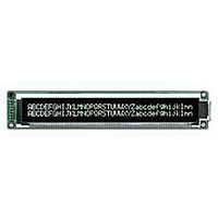
DMF-5005NY-LY-AKE Optrex America Inc, DMF-5005NY-LY-AKE Datasheet - Page 7

DMF-5005NY-LY-AKE
Manufacturer Part Number
DMF-5005NY-LY-AKE
Description
GRAPH MODULE 64X240 LED W/CONTR
Manufacturer
Optrex America Inc
Series
DMF-5005r
Datasheet
1.DMF-5005NY-LY-AKE.pdf
(17 pages)
Specifications of DMF-5005NY-LY-AKE
Display Mode
Transmissive
Display Type
LCD - Monochrome
Viewing Area
132.00mm L x 39.00mm W
Backlight
LED - Yellow/Green
Dot Size
0.49mm W x 0.49mm H
Dot Pitch
0.53mm x 0.53mm
Dot Pixels
240 x 64
Interface
Parallel
Pixel Density
240 x 64
Fluid Type
STN
Module Size (w X H X T)
180 mm x 65 mm x 17.6 mm
Viewing Area (w X H)
132 mm x 39 mm
Backlighting
LED Yellow / Green
Background Color
Dark
Attached Touch Screen
No
Style
Monochrome
Lead Free Status / RoHS Status
Lead free / RoHS Compliant
Lead Free Status / RoHS Status
Lead free / RoHS Compliant, Lead free / RoHS Compliant
Other names
73-1157
DMF-5005NY-LY
OP64240NY
DMF-5005NY-LY
OP64240NY
Recommended
Contrast Ratio
Viewing Angle
Response
DMF5005NY-LY-AKE (CN) No.99-0201
3.Optical Specif ications
Note 1 :
Note 1 : Contrast ratio is definded as follows.
Note 2 : The time that the luminance level reaches 90% of the saturation level from 0% when ON
Note 3 : The time that the luminance level reaches 10% of the saturation level from 100% when OFF
Note 4 : Definition of Driving Voltage V
3.1.LCD Driving Voltage
3.2.Optical Characteristics
LCD Driving Voltage
Time
Parameter
Parameter
minimum and maximum shows tolerance of the operating voltage. The specified contrast ratio and
response time are not guaranteed over the entire range.
L
L
signal is applied.
signal is applied.
Assuming that the typical driving waveforms shown below are applied to the LCD Panel at
1/A Duty - 1/B Bias ( A : Duty Number, B : Bias Number ). Driving voltage V
as follows.
Vth1 : The voltage V
Vth2 : The voltage V
ON
OFF
CR = L
V
Rise
Decay Note 3
Voltage (Applied actual waveform to LCD Module) for the best contrast. The range of
: Luminance of the ON segments
: Luminance of the OFF segments
D
V
the segment which the ON signal is applied to.
the segment which the OFF signal is applied to.
= (Vth1+Vth2) / 2
O-P
Note 1
Note 1
OFF
Note 2
1 / (
〈 ON SIGNAL 〉
/ L
ON
f
F
× A )
O-P
O-P
V
Symbol
Symbol
CC
T
T
that should provide 50% of the saturation level in the luminance at
that should provide 50% of the saturation level in the luminance at
CR
OFF
ON
-V
EE
Ta=25℃, 1/64 Duty, 1/9 Bias, V
D
θ= 0 ゚, φ=-゚
Conditions
Conditions
Ta=25℃
Ta=50℃
Ta= 0℃
-
-
OPTREX
OPTREX CORPORATION
1 /
〈 OFF SIGNAL 〉
f
F
Shown in 3.3
Min.
Min.
12.1
10.9
D
-
-
-
-
=13.0V (Note 4), θ= 0 ゚, φ=-゚
( B-2 ) × V
Typ.
13.0
Typ.
160
160
-
-
7
O-P
D
Max.
Max.
15.3
13.9
is definded
/ B
240
240
-
-
Page 7/17
Units
Units
ms
ms
V
V
V


