NHD-2.4-240320ZF-CTXI#-1 Newhaven Display, NHD-2.4-240320ZF-CTXI#-1 Datasheet - Page 21
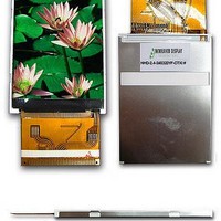
NHD-2.4-240320ZF-CTXI#-1
Manufacturer Part Number
NHD-2.4-240320ZF-CTXI#-1
Description
LCD DISP TFT 2.4" 240X320
Manufacturer
Newhaven Display
Datasheet
1.NHD-2.4-240320ZF-CTXI-1.pdf
(22 pages)
Specifications of NHD-2.4-240320ZF-CTXI#-1
Display Type
TFT - Color LCD
Display Mode
Transmissive
Viewing Area
36.72mm L x 48.96mm W
Backlight
LED - White
Dot Pitch
0.05mm x 0.15mm
Dot Pixels
240 x 320
Interface
Digital
Lead Free Status / RoHS Status
Lead free / RoHS Compliant
Dot Size
-
Lead Free Status / Rohs Status
Details


STANDARD
(4) When using an electric screwdriver to attach LCM, the screwdriver should be of ground potentiality to minimize as much as
(2) Before remove LCM from its packing case or incorporating it into a set, be sure the module and your body have the same
DOC.
(1) Do not alter, modify or change the the shape of the tab on the metal frame.
(2) Do not make extra holes on the printed circuit board, modify its shape or change the positions of components to be
(3) Do not damage or modify the pattern writing on the printed circuit board.
(4) Absolutely do not modify the zebra rubber strip (conductive rubber) or heat seal connector.
(5) Except for soldering the interface, do not make any alterations or modifications with a soldering iron.
(6) Do not drop, bend or twist LCM. In particular, do not forcibly pull or bend the I/O cable or the backlight cable.
(7) In order to avoid the cracking of the FPC,you should to pay attention to the area of FPC where the FPC was bent .the edge
(1) Make certain that you are grounded when handing LCM. To minimize the performance degradation of the LCD modules
(3) When soldering the terminal of LCM, make certain the AC power source for the soldering iron does not leak.
(5) As far as possible make the electric potential of your work clothes and that of the work bench the ground potential.
(6) To reduce the generation of static electricity be careful that the air in the work is not too dried. A relative humidity of
(1) Viewing angle varies with the change of liquid crystal driving voltage (VO). Adjust VO to show the best contrast.
(2) Driving the LCD in the voltage above the limit shortens its life.
(3) If the LCD modules have been operating for a long time showing the same display patterns, the display patterns may
(4) Response time is greatly delayed at temperature below the operating temperature range. However, this does not mean the
(5) If the display area is pushed hard during operation, the display will become abnormal. However, it will return to normal if it is
(6) Condensation on terminals can cause an electrochemical reaction disrupting the terminal circuit. Therefore, it must be used
(7) When turning the power on, input each signal after the positive/negative voltage becomes stable.
module or making any alterations or modifications to it.
attached.
of coverlay;the area of surface of Ni-Au plating,the area of soldering land,the area of through hole.
ordinary CMOS IC.
resulting from destruction caused by static electricity etc., exercise care to avoid holding the following sections when handling
the modules. - Exposed area of the printed circuit board. - Terminal electrode sections.
electric potential.
50%-60% is recommended.
remain on the screen as ghost images and a slight contrast irregularity may also appear. A normal operating status can be
regained by suspending use for some time. It should be noted that this phenomenon does not adversely affect performance
reliability.
LCD will be out of the order. It will recover when it returns to the specified temperature range.
turned off and then back on.
under the relative condition of 40°C , 50% RH.
possible any transmission of electromagnetic waves produced sparks coming from the commutator of the motor.
Since this module uses a CMOS LSI, the same careful attention should be paid to electrostatic discharge as for an
PRODUCT
SPEC.
MODULE
NO.
PAGE
20
Related parts for NHD-2.4-240320ZF-CTXI#-1
Image
Part Number
Description
Manufacturer
Datasheet
Request
R

Part Number:
Description:
LCD DISPLAY TFT 2.4" 240X320 WHT
Manufacturer:
Newhaven Display
Datasheet:

Part Number:
Description:
LCD DISPL TFT 2.4" 240X320 WH+TP
Manufacturer:
Newhaven Display
Datasheet:
Part Number:
Description:
LCD DISP TFT 2.4" 240X320 B/L
Manufacturer:
Newhaven Display
Datasheet:

Part Number:
Description:
LCD DISP TFT 2.4" 240X320 B/L
Manufacturer:
Newhaven Display
Datasheet:

Part Number:
Description:
LCD DISPLAY TFT 2.4" 320X240 WHT
Manufacturer:
Newhaven Display

Part Number:
Description:
LCD DISP TFT 2.4" 240X320
Manufacturer:
Newhaven Display
Datasheet:

Part Number:
Description:
TFT Displays & Accessories 2.4 240 x 320 DPI 60.26 x 42.72 x 3.9
Manufacturer:
Newhaven Display
Datasheet:
Part Number:
Description:
TFT Displays & Accessories 2.4 240 x 320 DPI w/ Touch Panel
Manufacturer:
Newhaven Display
Datasheet:

Part Number:
Description:
DISPLAY VFD ALPHA 1X20 6.5MM
Manufacturer:
Newhaven Display
Datasheet:

Part Number:
Description:
DISPLAY VFD ALPHA 1X16 5MM
Manufacturer:
Newhaven Display
Datasheet:

Part Number:
Description:
DISPLAY VFD 7-SEG 1X9 9.7MM
Manufacturer:
Newhaven Display
Datasheet:

Part Number:
Description:
DISPLAY VFD 7-SEG 1X6 20MM
Manufacturer:
Newhaven Display
Datasheet:

Part Number:
Description:
DISPLAY VFD 7-SEG 1X19 11MM
Manufacturer:
Newhaven Display
Datasheet:

Part Number:
Description:
DISPLAY VFD 7-SEG 1X3 8MM
Manufacturer:
Newhaven Display
Datasheet:

Part Number:
Description:
DISPLAY VFD CUSTOM DVD
Manufacturer:
Newhaven Display
Datasheet: