F-51405GNB-LW-ANN Optrex America Inc, F-51405GNB-LW-ANN Datasheet - Page 14
F-51405GNB-LW-ANN
Manufacturer Part Number
F-51405GNB-LW-ANN
Description
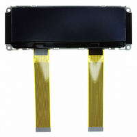
LCD GRAPHIC 240X64 BLU/WHT LED
Manufacturer
Optrex America Inc
Series
F-51405r
Datasheet
1.F-51405GNB-LW-ANN.pdf
(22 pages)
Specifications of F-51405GNB-LW-ANN
Display Type
LCD - Monochrome
Display Mode
Transmissive
Viewing Area
130.20mm L x 36.70mm W
Backlight
LED - White
Dot Pitch
0.53mm x 0.53mm
Dot Pixels
240 x 64
Lead Free Status / RoHS Status
Lead free / RoHS Compliant
Interface
-
Dot Size
-
Lead Free Status / Rohs Status
Details
Other names
73-1314


CN3
No.
F-51405GNB-LW-ANN (AN) No. 2005-0310
33
34
35
36
1
2
When installing the COG,it is necessary to duly consider the fact that there exists a resistance
of the ITO wiring occurring between the driver chip and the externally connected parts (such as
capacitors and resistors).By the influence of this resistance, non-conformity may occur with the
indications on the liquid crystal display.
Please use circuit by outside power supply.
4.2. Recommendation Example of the circuit
CATHODE
ANODE
Symbol
C86
P/S
IRS
NC
outside
supply
power
Interface Mode Select Signal H : 68 series L : 80 series
Parallel/Serial Data Select Signal H : Parallel L : Serial
This terminal selects the resistors for the V5 voltage level adjustment.
Master (CN1)
Slave (CN2)
Non-connection
LED Anode Terminal
LED Cathode Terminal
V
IRS=”H” :Use the internal resistors
IRS=”L” :Do not use the internal resistors. The V5 Voltage level is
requlated by an external resistive voltage divider attached to the VR
terminal.
IRS=NC (IRS is pulled to VDD.)
DD
V
V
SS
SS
V
V
CAP3-
CAP1+
CAP1-
CAP2-
V
V
V1
V2
V3
V4
V5
V
SS2
OUT
5
DD
R
OPTREX CORPORATION
IRS
Function
M/S
V
DD
Page 14/22
Related parts for F-51405GNB-LW-ANN
Image
Part Number
Description
Manufacturer
Datasheet
Request
R

Part Number:
Description:
LCD GRAPHIC 240X64 BLU/WHT LED
Manufacturer:
Optrex America Inc
Datasheet:

Part Number:
Description:
LCD 6.5" TFT MOD 640X480 VGA
Manufacturer:
Optrex America Inc

Part Number:
Description:
LCD Graphic Display Modules & Accessories OPTREX
Manufacturer:
Optrex America Inc

Part Number:
Description:
LCD MODULE 16X2 CHARACTER
Manufacturer:
Optrex America Inc
Datasheet:

Part Number:
Description:
LCD MOD CHAR 20X2 TRANSMISSIVE
Manufacturer:
Optrex America Inc
Datasheet:

Part Number:
Description:
LCD MODULE 16X1 W/LED BACKLIGHT
Manufacturer:
Optrex America Inc
Datasheet:

Part Number:
Description:
LCD MOD CHAR 16X2 WHT TRANSFLECT
Manufacturer:
Optrex America Inc
Datasheet:

Part Number:
Description:
LCD MODULE 20X2 GREEN CHARACTER
Manufacturer:
Optrex America Inc
Datasheet:

Part Number:
Description:
LCD MODULE 20X2 BLUE CHARACTER
Manufacturer:
Optrex America Inc
Datasheet:

Part Number:
Description:
LCD MODULE 20X2 WHITE CHARACTER
Manufacturer:
Optrex America Inc
Datasheet:
Part Number:
Description:
LCD MOD 16X2 CHARAC TRANS W/LED
Manufacturer:
Optrex America Inc
Datasheet:

Part Number:
Description:
LCD MOD CHAR 20X4 WHT TRANSFLECT
Manufacturer:
Optrex America Inc
Datasheet:

Part Number:
Description:
LCD MODULE 16X2 HI CONT STD LED
Manufacturer:
Optrex America Inc

Part Number:
Description:
LCD MOD CHAR 20X4 WHT TRANSMISS
Manufacturer:
Optrex America Inc
Datasheet:

Part Number:
Description:
LCD MOD CHAR 16X2 WHT TRANSMISS
Manufacturer:
Optrex America Inc
Datasheet: