NHD-C128128BZ-FSW-GBW Newhaven Display, NHD-C128128BZ-FSW-GBW Datasheet
NHD-C128128BZ-FSW-GBW
Specifications of NHD-C128128BZ-FSW-GBW


Related parts for NHD-C128128BZ-FSW-GBW


NHD-C128128BZ-FSW-GBW Summary of contents
Page 1
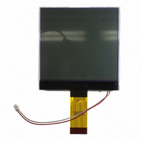
... NHD‐C128128BZ‐FSW‐GBW COG (Chip‐On‐Glass) Liquid Crystal Display Module NHD‐ Newhaven Display C128128‐ 128 x 128 pixels BZ‐ Model F‐ ...
Page 2
Document Revision History Revision Date 0 6/17/2007 1 9/23/2009 2 10/14/2009 3 11/20/2009 4 3/4/2011 Functions and Features • 128 x 128 pixels • Built‐in ST7528 controller • +3.0V power supply • 1/128 duty cycle; 1/12 bias • RoHS Compliant ...
Page 3
... Speci cation: 1). Driving: 1/128 Duty, 1/12 Bias, VLCD: 13.5V 2). Viewing Direction: 6 o’clock 3). Display mode: STN/Positive/Trans ective/Gray mode 4). Operating temp. : Storage temp. : 5). Driver: ST7528 Vdd:3V 6). Edge Backlight: White color, 3~3.3V, Current: 75~90mA 7). RoHS Compliant 30 1 Newhaven Display NHD-C128128BZ-FSW-GBW ...
Page 4
Pin Description and Wiring Diagram Pin No. Symbol External Connection 1 PS0 Input 2 PS1 Input 3 PS2 Input 4 CSB MPU 5 RST MPU 6 A0 MPU 7 RW(WR) MPU 8 E(RD) MPU 9‐16 DB0‐DB7 MPU 17,18 VDD Power Supply 19,20 Vss Power Supply 21 V ...
Page 5
Parallel/Serial Select Table PS2 PS1 PS0 Interface mode L L H Parallel 80 L H H Parallel 68 L L L 3Line Serial L H L 4Line Serial *Cannot read data from RAM in 4‐line, 3‐line, or IIC interface. *In 4‐line or 3‐line interface, DB0‐DB5, E, and RW must be tied High or Low *In IIC or 3‐line interface, A0 must be tied High or Low Electrical Characteristics Item Operating Temperature Range Storage Temperature Range Supply Voltage Supply Current Supply for LCD (contrast) “H” Level input “L” Level input “H” Level output “L” Level output Backlight supply voltage Backlight supply current ...
Page 6
[6] ...
Page 7
Table of Commands [7] ...
Page 8
[8] ...
Page 9
Example Initialization Program /*************************************************************/ /*************************************************************/ void write_command(unsigned char datum) { A0=0; E=1; bus=datum; CSB=0; RW=0; RW=1; CSB=1; ...
Page 10
/*** start settings for 16‐level grayscale ***/ [10] ...
Page 11
[11] ...
Page 12
write_command(0x35); write_command(0xb4); write_command(0x38); write_command(0xb5); write_command(0x38); write_command(0xb6); write_command(0x38); write_command(0xb7); write_command(0x38); write_command(0xb8); write_command(0x3a); write_command(0xb9); write_command(0x3a); write_command(0xba); write_command(0x3a); write_command(0xbb); write_command(0x3a); write_command(0xbc); write_command(0x3c); write_command(0xbd); write_command(0x3c); write_command(0xbe); write_command(0x3c); write_command(0xbf); write_command(0x3c); //end settings for 16‐level grayscale write_command(0x38); write_command(0x74); write_command(0xaf); //Display ON } /*************************************************************/ /*************************************************************/ ...
Page 13
Quality Information Test Item High Temperature storage storage temperature for a long time. Low Temperature storage Endurance test applying the low storage temperature for a long time. High Temperature Endurance test applying the electric stress Operation (voltage & current) and the high thermal stress for a long time. Low Temperature Endurance test applying the electric stress Operation (voltage & current) and the low thermal stress for a long time. High Temperature / Endurance test applying the electric stress Humidity Operation (voltage & current) and the high thermal with high humidity stress for a long time. Thermal Shock resistance Endurance test applying the electric stress (voltage & current) during a cycle of low and high thermal stress. Vibration test Endurance test applying vibration to simulate transportation and use. Static electricity test Endurance test applying electric static discharge. Note 1: No condensation to be observed. Note 2: Conducted after 4 hours of storage at 25 Note 3: Test performed on product itself, not inside a container. ...