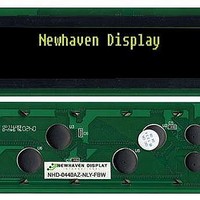
NHD-0440AZ-NLY-FBW Newhaven Display, NHD-0440AZ-NLY-FBW Datasheet

NHD-0440AZ-NLY-FBW
Specifications of NHD-0440AZ-NLY-FBW
Related parts for NHD-0440AZ-NLY-FBW
NHD-0440AZ-NLY-FBW Summary of contents
Page 1
... NHD‐0440AZ‐NLY‐FBW‐C6 Character Liquid Crystal Display Module NHD‐ Newhaven Display 0440‐ 4 lines x 40 characters AZ‐ Model N‐ Transmissive ...
Page 2
Document Revision History Revision Date 0 10/21/2008 1 10/29/2009 2 11/17/2009 3 12/16/2009 Functions and Features • 4 lines x 40 characters • 2 Built‐in controllers (SPLC780D or equivalent) • +5.0V Power Supply • 1/16 duty, 1/5 bias • RoHS compliant Description Initial Release User Guide Reformat Updated Block diagram and initialization code Updated Backlight Supply Voltage and Current Changed by ...
Page 3
... Mechanical Drawing Newhaven Display NHD-0440AZ-NLY-FBW-C6 ...
Page 4
Pin Description and Wiring Diagram Pin No. Symbol External Connection 1‐4 DB7‐DB4 MPU 5‐8 DB3‐DB0 MPU 9 E1 MPU 10 R/W MPU 11 RS MPU 12 V0 Power Supply 13 Vss Power Supply 14 VDD Power Supply 15 E2 MPU 16 NC ‐ 17 LED+ Power Supply 18 LED‐ ...
Page 5
Electrical Characteristics Item Operating Temperature Range Storage Temperature Range Supply Voltage Supply Current Supply for LCD (contrast) “H” Level input “L” Level input “H” Level output “L” Level output Backlight Supply Voltage Backlight Supply Current Optical Characteristics Item Viewing Angle – Vertical (top) Viewing Angle – Vertical (bottom) Viewing Angle – Horizontal (left) Viewing Angle – Horizontal (right) Contrast Ratio Response Time (rise) Response Time (fall) Controller Information Built‐in SPLC780D. Download specification at http://www.newhavendisplay.com/app_notes/SPLC780D.pdf ...
Page 6
Table of Commands ...
Page 7
Timing Characteristics Writing data from MPU to SPLC780D Reading data from SPLC780D to MPU ...
Page 8
Writing Data from MPU to SPLC780D. Reading Data from SPLC780D to MPU. ...
Page 9
Built‐in Font Table ...
Page 10
Example Initialization Program /************************************************************************/ void command1(char i) //Top half of the display { P1 = i; W = 0; RS = 0; E1 = 1; delay(2); E1 = 0; } void command2(char i) //Bottom half of the display { P1 = i; W = 0; RS = 0; E2 = 1; delay(2); E2 = 0; } /************************************************************************/ void writedata1(char i) //Top half of the display { P1 = i; W = 0; RS = 1; E1 = 1; delay(2); E1 = 0; } void writedata2(char i) //Bottom half of the display { P1 = i; ...
Page 11
W = 0; RS = 1; E2 = 1; delay(2); E2 = 0; } /************************************************************************/ void init_LCD() { delay(15); command1(0x30); //Wake up command2(0x30); delay(5); command1(0x30); //Wake up command2(0x30); delay(5); command1(0x30); //Wake up command2(0x30); delay(5); command1(0x38); //Function Set = 8bit mode; 2‐line; 5x8 command2(0x38); command1(0x08); //Turn off display command2(0x08); command1(0x01); //Clear display command2(0x01); command1(0x06); //Entry mode cursor increment command2(0x06); command1(0x0c); //Turn on display; no cursor command2(0x0c); } /************************************************************************/ ...
Page 12
Quality Information Test Item High Temperature storage storage temperature for a long time. Low Temperature storage Endurance test applying the low storage temperature for a long time. High Temperature Endurance test applying the electric stress Operation (voltage & current) and the high thermal stress for a long time. Low Temperature Endurance test applying the electric stress Operation (voltage & current) and the low thermal stress for a long time. High Temperature / Endurance test applying the electric stress Humidity Operation (voltage & current) and the high thermal with high humidity stress for a long time. Thermal Shock resistance Endurance test applying the electric stress (voltage & current) during a cycle of low and high thermal stress. Vibration test Endurance test applying vibration to simulate transportation and use. Static electricity test Endurance test applying electric static discharge. Note 1: No condensation to be observed. Note 2: Conducted after 4 hours of storage at 25 Note 3: Test performed on product itself, not inside a container. Precautions for using LCDs/LCMs See Precautions at www.newhavendisplay.com/specs/precautions.pdf ...


