IS-L0251-C NKK Switches, IS-L0251-C Datasheet
IS-L0251-C
Specifications of IS-L0251-C


Related parts for IS-L0251-C


IS-L0251-C Summary of contents
Page 1
... IS-C1603 Intelligent Controller Users Manual NKK Switches makes no warranty for the use of these products and assumes no responsibility for any errors, which may appear in this document, nor does it make a commitment to update the information contained herein. Smart Switch is trademark of NKK Switches. IS-C1603 Intelligent Controller Users Manual C.doc Toll Free 1.877.2BUYNKK (877.228.9655) • ...
Page 2
... IS-C1603 Intelligent Controller Users 7850 East Gelding Drive • Scottsdale, AZ 85260-3420 IS-C1603 Intelligent Controller Users Manual C.doc Toll Free 1.877.2BUYNKK (877.228.9655) • Phone 480.991.0942 • Fax 480.998.1435 Manual www.nkkswitches.com • Email engineering@nkkswitches.com Page 0110 ...
Page 3
... East Gelding Drive • Scottsdale, AZ 85260-3420 1. General Controller Features The IS-C1603 controls 16 LCD 36x24 switches/ displays. The IS-C1603 is designed to be used in many different applications. There is total flexibility with user-defined features that allow the controllers to be programmed for specific applications. The user defined data and set up are stored in a non volatile memory and specify the way the system behaves ...
Page 4
... The following is a list of compatible Logic Boards and switches. RGB, 4 bit: A. IS-L0204-C Two LCD 36x24 RGB, 4 bit B. IS-L0251-C Two LCD 36x24 RGB Display, 4 bit C. IS-L0271-C Two LCD 36x24 RGB Compact, 4 bit D. IS-L0107-IS15ABFP4RGB One LCD 36x24 RGB, 4 bit. ...
Page 5
... Each Page has a Legend Block (image data), LCD/LED code, control code, Attribute block, and user- defined look-up tables. Upon power-up the data from Page 1 is displayed on switch 1, the data from Page 2 is displayed on switch 2 and Page 16 which is displayed on switch 16. ...
Page 6
... HEX format from user-defined image press look-up table associated with the Pointer bit 5 of FLAG-A is enabled (default: enabled) and bit 2 of FLAG-B is zero (default: 0) then do the following: 1. Use current Pointer to find the associated Address, if the viewing angle/ brightness code is not zero, then increase or decrease the brightness accordingly ...
Page 7
... A block of 120 bytes (subset of the Legend Block). There are five bytes of data for each pixel-row of LCD module. The least significant nibble of the fifth byte is not used. The most significant bit of the first byte will be displayed as the leftmost pixel of pixel-row of LCD module. ...
Page 8
... B. If the byte is not a command ignored. When the controller executes a subroutine and expects additional information timer is set. If the expected data byte is not received in 50ms, the controller transmits 6EH and terminates the routine the byte value is not acceptable (invalid range, option, etc.), the controller transmits 6EH and terminates the routine ...
Page 9
... This command uploads the Pointer value in ASCII HEX format. command format: 2EH transmit format: (xxH) (xxH) [Module #] is one byte with value of 01H to 10H and must be sent in ASCII hex format. IS-C1603 Intelligent Controller Users Manual C.doc Toll Free 1.877.2BUYNKK (877.228.9655) • Phone 480.991.0942 • Fax 480.998.1435 Manual ...
Page 10
... Pointer is left unchanged. command format: 2DH transmit format: (xxH) (xxH) [Pointer Block bytes of address values for the Pointers and must be sent in ASCII HEX format. Command to download one Pointer value to specified Module This command downloads the Pointer value for specified module. command format: 2EH ...
Page 11
... This command sets the 16 LCD/LED codes in the LCD/LED refresh buffer. If the value of a LCD/LED code is zero, the corresponding code in the refresh buffer is left unchanged update is desired for the value of zero, Bit 7 should be set to 1. Command to download one LCD/LED Code to specified Module This command sets the LCD/LED code for specified module ...
Page 12
... FFH and must be sent in ASCII HEX format. [09H] is two byte and must be sent in ASCII HEX format (30 39). [LCD/LED code] is one byte with value of 01H to FFH and must be sent in ASCII HEX format. The LCD/LED code is not transferred to LCD/LED code refresh block. ...
Page 13
... Addresses bytes of Pointer values indicating what Addresses and associated Images and Page data will be displayed upon power up or reboot. The values are from 01H to FFH and must be sent in ASCII HEX format. The default values are 01H, 02H, 03H, …, …, 0EH, 0FH, 10H. ...
Page 14
... FFH and must be sent in ASCII HEX format. [0FH byte and must be sent in ASCII HEX format (30 46). [ASCII string bytes and is a string of font 5x7 look-up table indexes. It must be sent in HEX format. Command to display 6 characters for the third line of font 5x7 This command sets the image data at a specified address with the third line of 6 characters of font 5x7 ...
Page 15
... FFH and must be sent in ASCII HEX format. [0AH] is two byte and must be sent in ASCII HEX format (30 41). [ASCII string bytes and is a string of font 7x10 look-up table indexes. It must be sent in HEX format. Command to display 4 characters for the second line of font 7x10 This command sets the image data at a specified address with the second line of 4 characters of font 7X10 ...
Page 16
... FFH and must be sent in ASCII HEX format. [0DH] is two byte and must be sent in ASCII HEX format (30 44). [ASCII string bytes and is a string of font 7x10 look-up table indexes. It must be sent in HEX format. 5. Commands to download to Look-up tables. ...
Page 17
... All default values for this section are 00H. b. Font-Set Look-up Table: There are 256 fonts (00H to FFH) in each font set. The default bit map look-up tables are created for English ASCII characters (20H to 7FH). The default values for rest of the fonts are 00H. ...
Page 18
... The first byte is the top row of the character graphic and the 7th byte is the bottom row of the character graphic. The B7 of each byte of the character graphic data is the leftmost column of the character graphic. B2, B1 and B0 are not used and should be set to zero ...
Page 19
... ASCII HEX format (45 34). [Timer value] is one byte sent twice and must be sent in ASCII HEX format. The default value is 80H. The actual time is 20ms times this Timer value. To enable this feature, bit 7 of Flag-C must be set to 1 (the default is 0). ...
Page 20
... ASCII HEX format (45 39 Modules] is one byte with value of 01H to 10H and must be sent twice in ASCII HEX format. This command goes into effect after the following power up / reboot. 8. Setting the Flags The controller features can be customized based on customer requirements by manipulating the settings of the Flags ...
Page 21
... Flag Byte B [Option] = EDH (45 44) Flag Byte C [Flag Byte] is one byte and must be sent twice in ASCII HEX format. This command writes the downloaded flag data to storage memory. The changes go into effect after the following power up / reboot. Flag Byte A Default Value=63H Bit ...
Page 22
... B7=1 ---> Animated Image operation. A Module with a Pointer value above 127 (7FH) will have its image continuously step through 8 Addresses. The alternating addresses are as follow: 80H to 87H, 88H to 8FH, 90H to 97H,……,F0H to F7H,F8H to FFH The alternating time is determined based on two user-defined variables and a constant. Alternating time (20) (Animation Timer) (Animation Multiplier) Flag Byte B Default Value=60H ...
Page 23
... B4, B7 -->These two bits are for polling operation. Both bits must be set to 1 for proper operation. Use XON and XOFF for communication. The controller stops transmitting upon receiving 13H and resumes transmitting upon receiving 11H. The transmit buffer is 256 bytes. The data will be lost if more than 256 bytes transmitted. RS422 only. Flag Byte C Default Value=00H Bit ...
Page 24
... This command is for set-up/testing of the controller. The controller is put into the set-up mode, where any number of options may be transmitted. This is the only command where the timer between two consecutive received bytes is not set. The user must exit this mode by sending X (58H) or ESC (1BH recommended that the B6 of Flag set during the operation. ...
Page 25
... Option Reserved 47H IS-C1603 Intelligent Controller Users Manual C.doc Toll Free 1.877.2BUYNKK (877.228.9655) • Phone 480.991.0942 • Fax 480.998.1435 Manual www.nkkswitches.com • ...
Page 26
... IS-C1603 Intelligent Controller Users Manual C.doc Toll Free 1.877.2BUYNKK (877.228.9655) • ...
Page 27
... Option Serial Set-up Mode 53H [serial setup option] Controller is put into serial set-up mode. Once in serial set-up mode, only options for serial set-up are available. The mode is not changed until power-up or reset. 31H Select 9600 BAUD rate ...
Page 28
... Option Disable Switch Closure Beep 63H Controller sets the flag which disables the switch closure beep. The effect lasts for only the duration of the session. ……………………………………………………………………………………………………………………. ...
Page 29
... Option Disable Switch Press Reports (Default value) 67H Controller sets the flag which disables switch press reports (default value). The effect lasts for only the duration of the session. ……………………………………………………………………………………………………………………. ...
Page 30
... Option Disable Image Press Reports (Default value) 6BH Controller sets the flag which disables Image press reports (Default value). The effect lasts for only the duration of the session. ……………………………………………………………………………………………………………………. ...
Page 31
... Option Any non-option byte XXH Controller transmits 6EH and exits command 26H. IS-C1603 Intelligent Controller Users Manual C.doc Toll Free 1.877.2BUYNKK (877.228.9655) • Phone 480.991.0942 • Fax 480.998.1435 Manual www.nkkswitches.com • Email engineering@nkkswitches.com ...
Page 32
... Dimension: Board size: 4.500” x 4.200” (114.3 x 106.68 mm) Mounting holes: Four Hole size: .150” (3.81mm) Distance from edges of the board: .150” (3.81mm) IS-C1603 Intelligent Controller Users Manual C.doc Toll Free 1.877.2BUYNKK (877.228.9655) • Phone 480.991.0942 • Fax 480.998.1435 Manual www.nkkswitches.com • ...
Page 33
... East Gelding Drive • Scottsdale, AZ 85260-3420 Controls Overview POTB: Beeper Volume adjusts the volume of the beeper. JP2: Logic Board Header is the connector for the ribbon cable to the logic boards. Pin numbers much match up from connector to connector using Pin guide. 7x2 male header .1”x.1” spacing. ...
Page 34
... IS-C1603 Intelligent Controller Users 7850 East Gelding Drive • Scottsdale, AZ 85260-3420 Jumper Overview J3: JPR: J2: IS-C1603 Intelligent Controller Users Manual C.doc Toll Free 1.877.2BUYNKK (877.228.9655) • Phone 480.991.0942 • Fax 480.998.1435 Manual RS232: No jumper RS485: Jumper on pin 1 and pin 2 RS422: Jumper on pin 2 and pin 3 Unnecessary for programming ...
Page 35
... IS-C1603 Intelligent Controller Users 7850 East Gelding Drive • Scottsdale, AZ 85260-3420 Controller Schematic IS-C1603 Intelligent Controller Users Manual C.doc Toll Free 1.877.2BUYNKK (877.228.9655) • Phone 480.991.0942 • Fax 480.998.1435 Manual www.nkkswitches.com • Email engineering@nkkswitches.com Page 0110 ...
Page 36
... IS-C1603 Intelligent Controller Users 7850 East Gelding Drive • Scottsdale, AZ 85260-3420 Controller Schematic (continued) IS-C1603 Intelligent Controller Users Manual C.doc Toll Free 1.877.2BUYNKK (877.228.9655) • Phone 480.991.0942 • Fax 480.998.1435 Manual www.nkkswitches.com • Email engineering@nkkswitches.com Page 0110 ...
Page 37
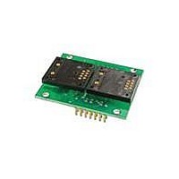
... IS-C1603 Intelligent Controller Users 7850 East Gelding Drive • Scottsdale, AZ 85260-3420 Two LCD 36x24 Resolution SmartSwitch, 36X24 RGB, logic board IS-C1603 Intelligent Controller Users Manual C.doc Toll Free 1.877.2BUYNKK (877.228.9655) • Phone 480.991.0942 • Fax 480.998.1435 Manual www.nkkswitches.com • Email engineering@nkkswitches.com ...
Page 38
... IS-C1603 Intelligent Controller Users 7850 East Gelding Drive • Scottsdale, AZ 85260-3420 Two LCD 36x24 SmartSwitch, 36X24 bicolor, logic board IS-C1603 Intelligent Controller Users Manual C.doc Toll Free 1.877.2BUYNKK (877.228.9655) • Phone 480.991.0942 • Fax 480.998.1435 Manual www.nkkswitches.com • Email engineering@nkkswitches.com Page ...
Page 39
... IS-C1603 Intelligent Controller Users 7850 East Gelding Drive • Scottsdale, AZ 85260-3420 Board photo IS-C1603 Intelligent Controller Users Manual C.doc Toll Free 1.877.2BUYNKK (877.228.9655) • Phone 480.991.0942 • Fax 480.998.1435 Manual www.nkkswitches.com • Email engineering@nkkswitches.com Page 0110 ...
Page 40
... Byte An eight bit hex value ranging from 00H to FFH (Decimal 0 to 255). The bit format of a byte is: ( B0) where B7 is most significant and bit B0 is least significant bit. Nibble/Hex digit A four bit value ranging from 0H to FH. A byte consists of two nibbles. ...
Page 41
... After you install the MTK software follow the following instructions to program the microcontroller: 1. Disconnect the switches from the controller at JP2. 2. Install a jumper on JPR connector (top right side of the board). This will put the microcontroller into programming mode. 3. Run MTK software. ...
Page 42
... The value of each digit is equal to the digit with ((Digit order) -1) zeros in front. All the operations that we use on base 10 numbering system such as addition, subtraction, multiplication, division… works the same for all the numbering systems. The difference is the carry over will be based on the base-number of the numbering system instead of 10. ...
Page 43
... To convert a decimal number to base-2 number ---divide the decimal number by 2, the remainder is the first digit of the base-2 number --- continue dividing quotient by 2 and put the remainder as the next digit until the quotient is equal 0. Example: Convert the decimal number 21 to base-2 21 divide with 1 remainder ...
Page 44
... East Gelding Drive • Scottsdale, AZ 85260-3420 Base-16 numbering system Communicating base-2 numbers is difficult for human because of all zero’s and one’s. To make it easier to present computer data, hexadecimal or base-16 numbering system is used. Four digit of base-2 numbering system convert to one digit of base-16 numbering system. Since we did not have digits for 10, 11, 12, 13, 14 and 15, they were assigned letters and F respectively ...
Page 45
... B = 1011 A5B hex = 1010 0101 1011 binary Converting binary to hex is as easy as replacing each 4 digit of binary to equivalent digit of hex. If the binary digits are not multiple of 4 for grouping, add enough zero to the left to make them multiple of 4. Example: Convert 0111 1010 1111 binary to hex ...