MT16VDDF12864HG-40BF2 Micron Technology Inc, MT16VDDF12864HG-40BF2 Datasheet - Page 18
MT16VDDF12864HG-40BF2
Manufacturer Part Number
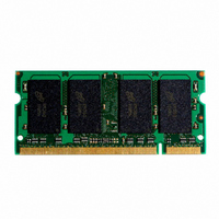
MT16VDDF12864HG-40BF2
Description
MODULE DDR SDRAM 1GB 200-SODIMM
Manufacturer
Micron Technology Inc
Specifications of MT16VDDF12864HG-40BF2
Memory Type
DDR SDRAM
Memory Size
1GB
Speed
400MT/s
Package / Case
200-SODIMM
Main Category
DRAM Module
Sub-category
DDR SDRAM
Module Type
200SODIMM
Device Core Size
64b
Organization
128Mx64
Total Density
1GByte
Chip Density
512Mb
Maximum Clock Rate
400MHz
Operating Supply Voltage (typ)
2.6V
Operating Current
1.6A
Number Of Elements
16
Operating Supply Voltage (max)
2.7V
Operating Supply Voltage (min)
2.5V
Operating Temp Range
0C to 70C
Operating Temperature Classification
Commercial
Pin Count
200
Mounting
Socket
Lead Free Status / RoHS Status
Contains lead / RoHS non-compliant


Notes
pdf: 09005aef80b57837, source: 09005aef80b577fa
DDAF16C64_128x64HG.fm - Rev. D 9/04 EN
10. I
11. This parameter is sampled. V
1. All voltages referenced to V
2. Tests for AC timing, I
3. Outputs measured with equivalent load:
4. AC timing and I
5. The AC and DC input level specifications are as
6. V
7. V
8. I
9. Enables on-chip refresh and address counters.
characteristics may be conducted at nominal ref-
erence/supply voltage levels, but the related spec-
ifications and device operation are guaranteed for
the full voltage range specified.
swing of up to 1.5V in the test environment, but
input timing is still referenced to V
crossing point for CK/CK#), and parameter speci-
fications are guaranteed for the specified AC input
levels under normal use conditions. The mini-
mum slew rate for the input signals used to test
the device is 1V/ns in the range between V
and V
defined in the SSTL_2 Standard (i.e., the receiver
will effectively switch as a result of the signal
crossing the AC input level, and will remain in that
state as long as the signal does not ring back
above [below] the DC input LOW [HIGH] level).
ting device and to track variations in the DC level
of the same. Peak-to-peak noise (non-common
mode) on V
DC value. Thus, from V
±25mV for DC error and an additional ±25mV for
AC noise. This measurement is to be taken at the
nearest V
system supply for signal termination resistors, is
expected to be set equal to V
variations in the DC level of V
rates. Specified values are obtained with mini-
mum cycle time at CL = 3 for -40B with the out-
puts open.
properly initialized, and is averaged at the defined
cycle rate.
V
DD
DD
REF
TT
DD
Q = +2.5V ±0.2V, V
is not applied directly to the device. V
is dependent on output loading and cycle
specifications are tested after the device is
is expected to equal V
IH
(AC).
REF
Output
(V
REF
OUT
bypass capacitor.
)
may not exceed ±2 percent of the
DD
V
DD
tests may use a V
TT
REF
50
30pF
, and electrical AC and DC
Reference
Point
DD
= V
SS
DD
Q/2, V
.
SS
REF
Q/2 of the transmit-
REF
DD
, f = 100 MHz, T
.
and must track
= +2.5V ±0.2V,
REF
REF
is allowed
(or to the
IL
-to-V
TT
IL
(AC)
is a
A
IH
=
18
12. For slew rates less than 1 V/ns and greater than or
13. The CK/CK# input reference level (for timing ref-
14. Inputs are not recognized as valid until V
15. The output timing reference level, as measured at
16. Transitions occur in the same access time win-
17. The intent of the Don’t Care state after completion
18. This is not a device limit. The device will operate
19. It is recommended that DQS be valid (HIGH or
20. MIN (
21. The refresh period 64ms. This equates to an aver-
25°C, V
0.2V. DM input is grouped with I/O pins, reflecting
the fact that they are matched in loading.
equal to 0.5 V/ns. If slew rate is less than 0.5 V/ns,
timing must be derated:
per each 100mV/ns reduction in slew rate from
500mV/ns, while
exceeds 4.5 V/ns, functionality is uncertain.
erenced to CK/CK#) is the point at which CK and
CK# cross; the input reference level for signals
other than CK/CK# is V
lizes. Exception: during the period before V
stabilizes, CKE 0.3 x V
the timing reference point indicated in Note 3, is
V
dows as data valid transitions. These parameters
are not referenced to a specific voltage level, but
specify when the device output is no longer driv-
ing (
of the postamble is the DQS-driven signal should
either be HIGH, LOW, or high-Z and that any sig-
nal transition within the input switching region
must follow valid input requirements. If DQS tran-
sitions high [above V
not transition to LOW below V
to
with a negative value, but system performance
could be degraded due to bus turnaround.
LOW) on or before the WRITE command. The
case shown (DQS going from high-Z to logic LOW)
applies when no WRITEs were previously in
progress on the bus. If a previous WRITE was in
progress, DQS could be HIGH during this time,
depending on
smallest multiple of
absolute value for the respective parameter.
(MAX) for I
ple of
value for
age refresh rate of 7.8125µs. However, an AUTO
REFRESH command must be asserted at least
once every 70.3µs; burst refreshing or posting by
512MB, 1GB (x64, DR) PC3200
Micron Technology, Inc., reserves the right to change products or specifications without notice.
TT
t
DQSH (MIN).
.
t
RPST,
t
RC or
OUT
t
CK that meets the maximum absolute
t
RAS.
(DC) = V
t
DD
HZ) or begins driving (
200-PIN DDR SODIMM
t
RFC) for I
t
measurements is the largest multi-
DQSS.
t
IH is unaffected. If slew rate
DD
t
CK that meets the minimum
IH
Q/2, V
REF
DD
(DC) (MIN)] then it must
t
DD
IS has an additional 50ps
Q is recognized as LOW.
.
measurements is the
OUT
IH
(peak to peak) =
©2004 Micron Technology, Inc.
(DC) MIN prior
t
LZ).
REF
stabi-
t
RAS
REF
Related parts for MT16VDDF12864HG-40BF2
Image
Part Number
Description
Manufacturer
Datasheet
Request
R

Part Number:
Description:
IC SDRAM 64MBIT 133MHZ 54TSOP
Manufacturer:
Micron Technology Inc
Datasheet:

Part Number:
Description:
IC SDRAM 64MBIT 5.5NS 86TSOP
Manufacturer:
Micron Technology Inc
Datasheet:
Part Number:
Description:
IC SDRAM 64MBIT 200MHZ 86TSOP
Manufacturer:
Micron Technology Inc
Datasheet:
Part Number:
Description:
IC SDRAM 64MBIT 133MHZ 54TSOP
Manufacturer:
Micron Technology Inc
Datasheet:
Part Number:
Description:
IC SDRAM 128MBIT 133MHZ 54TSOP
Manufacturer:
Micron Technology Inc
Datasheet:

Part Number:
Description:
IC SDRAM 256MBIT 133MHZ 90VFBGA
Manufacturer:
Micron Technology Inc
Datasheet:
Part Number:
Description:
IC SDRAM 128MBIT 133MHZ 54TSOP
Manufacturer:
Micron Technology Inc
Datasheet:
Part Number:
Description:
IC SDRAM 256MBIT 133MHZ 54TSOP
Manufacturer:
Micron Technology Inc
Datasheet:

Part Number:
Description:
IC DDR SDRAM 512MBIT 6NS 66TSOP
Manufacturer:
Micron Technology Inc
Datasheet:
Part Number:
Description:
IC SDRAM 128MBIT 167MHZ 86TSOP
Manufacturer:
Micron Technology Inc
Datasheet:
Part Number:
Description:
IC SDRAM 128MBIT 143MHZ 86TSOP
Manufacturer:
Micron Technology Inc
Datasheet:

Part Number:
Description:
SDRAM 256M-BIT 1.8V 54-PIN VFBGA
Manufacturer:
Micron Technology Inc
Datasheet:
Part Number:
Description:
IC SDRAM 128MBIT 143MHZ 86TSOP
Manufacturer:
Micron Technology Inc
Datasheet:

Part Number:
Description:
IC SDRAM 128MBIT 125MHZ 54VFBGA
Manufacturer:
Micron Technology Inc
Datasheet:
Part Number:
Description:
IC SDRAM 128MBIT 125MHZ 54VFBGA
Manufacturer:
Micron Technology Inc
Datasheet: