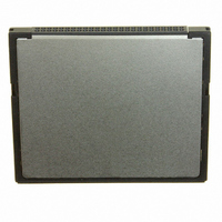
SMC128BFD6E NUMONYX, SMC128BFD6E Datasheet - Page 19

SMC128BFD6E
Manufacturer Part Number
SMC128BFD6E
Description
MEMORY CARD 128MB COMPACT FLASH
Manufacturer
NUMONYX
Datasheet
1.SMC04GBFK6E.pdf
(90 pages)
Specifications of SMC128BFD6E
Memory Size
128MB
Memory Type
CompactFLASH
Lead Free Status / RoHS Status
Lead free / RoHS Compliant
Available stocks
Company
Part Number
Manufacturer
Quantity
Price
SMCxxxBF
Table 9.
READY
(PC card memory mode)
–IREQ
(PC card I/O mode)
INTRQ
(True IDE mode)
–REG
(PC card memory mode)
–REG
(PC card I/O mode)
–DMACK
(True IDE mode)
RESET
(PC card memory mode)
RESET
(PC card I/O mode)
–RESET
(True IDE mode)
V
(PC card memory mode)
V
(PC card I/O mode)
V
(True IDE mode)
–VS1, –VS2
(PC card memory mode)
–VS1, –VS2
–VS1, –VS2
(PC card I/O mode)
(True IDE mode)
CC
CC
CC
Signal name
Signal descriptions (continued)
Dir.
O
O
I
I
13,38
33,40
Pin
37
44
41
Indicates whether the card is busy (Low), or ready to accept
a new data transfer operation (High). The host socket must
provide a pull-up resistor. At power-up and reset, the Ready
signal is held Low until the commands are completed. No
access should be made during this time. The Ready signal
is held High whenever the card has been powered up with
Reset continuously disconnected or asserted.
Interrupt request. It is strobed Low to generate a pulse
mode interrupt or held Low for a level mode interrupt.
Active High interrupt request to the host.
Used to distinguish between common memory and register
(attribute) memory accesses. High for common memory,
Low for attribute memory.
Must be Low during I/O cycles when the I/O address is on
the bus.
The –DMACK input signal is used to acknowledge DMA
transfers. It is asserted by the host in response to DMARQ
to initiate the transfer.
When DMA mode is disabled,
-DMACK signal.
If the host does not support DMA mode, but only True IDE
mode, this signal should be driven High or tied to V
host.
Resets the card (active High). The card is reset at power-up
only if this pin is left High or unconnected.
Same as PC card memory mode.
Hardware reset from the host (active Low).
+5 V, +3.3 V power.
Same for all modes.
Same for all modes.
Voltage sense signals.–VS1 is grounded so that the CIS
can be read at 3.3 volts and –VS2 is reserved by PCMCIA
for a secondary voltage.
Same for all modes.
Same for all modes.
Description
the card should ignore the
Electrical interface
CC
by the
19/90


