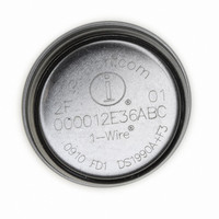
DS1977-F5# Maxim Integrated Products, DS1977-F5# Datasheet - Page 4

DS1977-F5#
Manufacturer Part Number
DS1977-F5#
Description
IBUTTON EEPROM 32KBit F5
Manufacturer
Maxim Integrated Products
Series
iButton®r
Datasheet
1.DS1977-F5.pdf
(29 pages)
Specifications of DS1977-F5#
Rohs Information
IButton RoHS Compliance Plan
Memory Size
32KB
Memory Type
EEPROM
Lead Free Status / RoHS Status
Lead free / RoHS Compliant
Available stocks
Company
Part Number
Manufacturer
Quantity
Price
APPLICATION
The DS1977 is an ideal device to store maintenance and inspection data of equipment or medical- and health-
related data in digitally readable format. Due to its small size and rugged enclosure the device can be carried with a
keyring to provide critical data in case of an emergency. The DS1977 can also serve as data shuttle to transport
fleet management and vending machine data to an access point for upload into a remote server for further
processing. Software for communication with the DS1977 is available for free download from the iButton website.
OVERVIEW
The block diagram in Figure 1 shows the relationships between the major control and memory sections of the
DS1977. The device has four main data components: 1) 64-bit lasered ROM, 2) 512-bit scratchpad and buffer, 3)
32KB EEPROM, and 4) two password buffers. The passwords can only be written and verified, but never be read.
The hierarchical structure of the 1-Wire protocol is shown in Figure 2. The bus master must first provide one of the
seven ROM function commands: 1) Read ROM, 2) Match ROM, 3) Search ROM, 4) Skip ROM, 5) Overdrive-Skip
ROM, 6) Overdrive-Match ROM or 7) Resume. Upon completion of an Overdrive ROM command byte executed at
standard speed, the device will enter Overdrive mode, where all subsequent communication occurs at a higher
speed. The protocol required for these ROM function commands is described in Figure 9. After a ROM function
command is successfully executed, the memory and control functions become accessible and the master may
provide any one of the six available commands. The protocol for these memory and control function commands is
described in Figure 7. All data is read and written least significant bit first.
Figure 1.
DS1977 BLOCK DIAGRAM
I/O
GENERATOR
CONTROL
CRC16
POWER
FUNCTION
SECURITY
CONTROL
CONTROL
MEMORY
MEMORY
ACCESS
ROM FUNCTION
4 of 29
CONTROL
SCRATCHPAD
AND BUFFER
EEPROM
64-BYTE
LASERED ROM
32KB
64-BIT
DS1977


