DS1985-F5+ Maxim Integrated Products, DS1985-F5+ Datasheet - Page 22

DS1985-F5+
Manufacturer Part Number
DS1985-F5+
Description
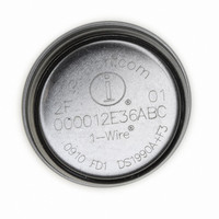
IBUTTON 16KBit ADD-ONLY F5
Manufacturer
Maxim Integrated Products
Series
iButton®r
Datasheet
1.DS1985-F5.pdf
(26 pages)
Specifications of DS1985-F5+
Rohs Information
IButton RoHS Compliance Plan
Memory Size
2KB
Memory Type
EPROM
Lead Free Status / RoHS Status
Lead free / RoHS Compliant
PROGRAM PULSE TIMING DIAGRAM Figure 11
CRC GENERATION
With the DS1985 there are two different types of CRCs (Cyclic Redundancy Checks). One CRC is an 8-
bit type and is stored in the most significant byte of the 64-bit ROM. The bus master can compute a CRC
value from the first 56 bits of the 64-bit ROM and compare it to the value stored within the DS1985 to
determine if the ROM data has been received error-free by the bus master. The equivalent polynomial
function of this CRC is: X
when reading the ROM of the DS1985. It is computed once at the factory and lasered into the ROM.
The other CRC is a 16-bit type, generated according to the standardized CRC16-polynomial function X
+ X
status memory. It is the same type of CRC as is used with NV RAM based iButtons to safeguard data
packets of the iButton File Structure. In contrast to the 8-bit CRC, the 16-bit CRC is always returned in
the complemented (inverted) form. A CRC-generator inside the DS1985 chip (Figure 12) will calculate a
new 16-bit CRC at every situation shown in the command flow chart of Figure 5.
The DS1985 provides this CRC-value to the bus master to validate the transfer of command, address, and
data to and from the bus master. When reading the data memory of the DS1985 with the Read Memory
command, the 16-bit CRC is only transmitted as the end of the memory is reached. This CRC is
generated by clearing the CRC generator, shifting in the command, low address, high address and every
data byte starting at the first addressed memory location and continuing until the end of the implemented
data memory is reached.
When reading the status memory with the Read Status command, the 16-bit CRC is transmitted when the
end of each 8-byte page of the status memory is reached. At the initial pass through the Read Status flow
chart the 16-bit CRC will be generated by clearing the CRC generator, shifting in the command byte, low
address, high address and the data bytes beginning at the first addressed memory location and continuing
until the last byte of the addressed EPROM Status data page is reached. Subsequent passes through the
Read Status flow chart will generate a 16-bit CRC that is the result of clearing the CRC generator and
then shifting in the new data bytes starting at the first byte of the next page of the EPROM Status data
field and continuing until the last byte of the page is reached.
15
+ X
LINE TYPE LEGEND:
2
+ 1. This CRC is used to safeguard user-defined EPROM data when reading data memory or
Bus master active high
(12V @ 10 mA)
Resistor pullup
8
+ X
5
+ X
4
+ 1. This 8-bit CRC is received in the true (non-inverted) form
22 of 26
16


