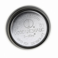
DS1990R-F3# Maxim Integrated Products, DS1990R-F3# Datasheet - Page 3

DS1990R-F3#
Manufacturer Part Number
DS1990R-F3#
Description
IBUTTON SERIAL NUMBER F3
Manufacturer
Maxim Integrated Products
Series
iButton®r
Datasheet
1.DS1990R-F3.pdf
(10 pages)
Specifications of DS1990R-F3#
Rohs Information
IButton RoHS Compliance Plan
Memory Size
8B
Memory Type
ROM
Lead Free Status / RoHS Status
Lead free / RoHS Compliant
Available stocks
Company
Part Number
Manufacturer
Quantity
Price
iButton CAN PHYSICAL SPECIFICATION
The block diagram in Figure 1 shows the major function
blocks of the device. The DS1990R takes the energy it
needs to operate from the IO line, as indicated by the
Figure 1. Block Diagram
Note 8:
Note 9:
Note 10: 30nC per 72 time slots at 5.0V pullup voltage with a 5kΩ pullup resistor and t
Note 11: The reset low time (t
Note 12: An additional reset or communication sequence cannot begin until the reset high time has expired.
Note 13: Presence pulse after POR is guaranteed by design, not production tested.
Note 14: ε in Figure 7 represents the time required for the pullup circuitry to pull the voltage on IO up from V
Note 15: δ in Figure 7 represents the time required for the pullup circuitry to pull the voltage on IO up from V
SIZE
WEIGHT (DS1990R)
The voltage on IO must be less than or equal to V
V
mask or conceal interrupt pulses if this device is used in parallel with a DS1994.
maximum duration for the master to pull the line low is t
threshold of the bus master. The actual maximum duration for the master to pull the line low is t
IH
is a function of the internal supply voltage.
_______________________________________________________________________________________
Detailed Description
See the Package Information section.
Ca. 2.5 grams
RSTL
) should be restricted to a maximum of 960µs to allow interrupt signaling. A longer duration could
IO
DS1990R
FUNCTION CONTROL
ROM
ILMAX
W1LMAX
whenever the master drives the line low.
parasite power block. The ROM function control unit
includes the 1-Wire interface and the logic to implement
the ROM function commands, which access 64 bits of
lasered ROM.
Serial Number iButton
+ t
F
- ε and t
PARASITE POWER
LASERED ROM
64-BIT
SLOT
W0LMAX
≤ 120µs.
+ t
F
- ε, respectively.
RLMAX
IL
IL
to V
to the input-high
+ t
IH
F
.
. The actual
3


