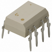
TLP621-2 Toshiba, TLP621-2 Datasheet

TLP621-2
Specifications of TLP621-2
Available stocks
Related parts for TLP621-2
TLP621-2 Summary of contents
Page 1
... The TLP621−2 offers two isolated channels in an eight lead plastic DIP, which the TLP621−4 provides four isolated channels in a sixteen plastic DIP. Collector−emitter voltage (min.) · · Current transfer ratio: 50% (min.) Rank GB: 100% (min.) Pin Configurations (top view) TLP621-2 TLP621 Anode 3 ...
Page 2
... Rank GR Rank BL Rank GB (None) TLP621-2 TLP621-4 Rank GB *1: Ex. rank GB: TLP621 (GB) (Note) Application type name for certification test, please use standard product type name, i.e. TLP621 (GB): TLP621 TLP621-2 (GB): TLP621-2 Made In Japan UL recognized E67349 BSI approved 6508, 7445 SEMKO approved 9735090 / 01 *2 UL1577 ...
Page 3
... When a VIDE0884 approved type is needed, please disignate the “Option (D4)” 7.62 mm pich standard type · Creepage distance : 6.4 mm (min.) Clearance : 6.4 mm (min.) Insulation thickness : 0.4 mm (min.) TLP621,TLP621−2,TLP621− 10.16 mm pich (LF2) type 8.0 mm (min) 8.0 mm (min) 0.4 mm (min) 3 2002-09-25 ...
Page 4
... Device considered a two terminal: LED side pins shorted together, and detector side pins shorted together. Recommended Operating Conditions Characteristic Supply voltage Forward current Collector current Operating temperature TLP621,TLP621−2,TLP621−4 Rating Symbol TLP621-2 TLP621 TLP621 -0.7 (Ta > 39°C) -0.5 (Ta = 25°C) ∆I /°C ...
Page 5
... (sat 0.2 mA (Ta = 25°C) Symbol Test Condition MHz 500 AC, 1 minute BV AC, 1 second, in oil S DC, 1 minute, in oil 5 TLP621,TLP621−2,TLP621−4 Min. Typ. Max. 1.0 1.15 1.3 — — 10 — 30 — 55 — — 7 — — — 10 100 — — 10 — MIn. Typ. ...
Page 6
... Fig. 1 Switching time test circuit I F (Ta = 25°C) Symbol Test Condition 100Ω off 1.9 kΩ (Fig. OFF TLP621,TLP621−2,TLP621−4 Min. Typ. Max. — 2 — — 3 — — 3 — — 3 — — 2 — — 15 — — 25 — 4.5V 0. OFF 2002-09-25 Unit µs µs ...
Page 7
... Duty cycle ratio DR TLP621,TLP621−2,TLP621−4 TLP621-2 TLP621-4 100 100 120 -20 0 Ambient temperature Ta (°C) TLP621-2 TLP621-4 120 100 100 120 -20 0 Ambient temperature Ta (°C) TLP621-2 TLP621-4 3000 1000 500 300 100 – 100 120 P – 100 60 80 120 I – Pulse width ≤ ...
Page 8
... Pulse forward voltage – 25°C 60 50mA 30mA 20mA 40 15mA P C (MAX.) 10mA 5mA Collector-emitter voltage V CE TLP621,TLP621−2,TLP621−4 -2.8 -2.4 -2.0 -1.6 -1.2 -0.8 -0.4 0.1 1.4 1.6 0 2.4 0 2.0 (V) Ambient temperature 0 (V) Collector-emitter voltage V 8 ∆V / ∆ ...
Page 9
... F I – 100 25mA 50 30 10mA 5mA 1mA 1 0 0.5mA 0.3 0.1 - Ambient temperature T (°C) a TLP621,TLP621−2,TLP621−4 500 300 Sample A 100 Sample 0.3 1 100 0. 5mA 1mA 0.16 0.12 0.08 0.04 0 -20 Ambient temperature T 1000 Ta = 25° 16mA 500 300 80 100 ...
Page 10
... TOSHIBA CORPORATION for any infringements of intellectual property or other rights of the third parties which may result from its use. No license is granted by implication or otherwise under any intellectual property or other rights of TOSHIBA CORPORATION or others. · The information contained herein is subject to change without notice. TLP621,TLP621−2,TLP621−4 10 000707EBC 2002-09-25 ...


