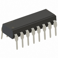
PS2503-4-A CEL, PS2503-4-A Datasheet

PS2503-4-A
Specifications of PS2503-4-A
Related parts for PS2503-4-A
PS2503-4-A Summary of contents
Page 1
... PS2502-1,-4,PS2502L-1,-4 DARLINGTON TRANSISTOR TYPE DESCRIPTION The PS2502-1, -4 and PS2502L-1, -4 are optically coupled isolators containing a GaAs light emitting diode and an NPN silicon darlington connected phototransistor. The PS2502-1, -4 are in a plastic DIP (Dual In-line Package) and the PS2502L-1, -4 are lead bending type (Gull- wing) for surface mount ...
Page 2
PACKAGE DIMENSIONS (UNIT : mm) DIP Type PS2502-1 4.6±0. 7. 15° +0.1 0.25 –0.05 1.25±0.15 0.50±0.10 0.25 M 2.54 Lead Bending Type PS2502L-1 4.6±0. 1.25±0.15 0.9±0.25 9.60±0.4 0.25 M ...
Page 3
MARKING EXAMPLE PS2502-1 No. 1 pin Mark 2502 NJ931 Week Assembled Year Assembled (Last 1 Digit) In-house Code CTR Rank Code Made in Japan Package New PKG No. 1 pin Mark Assembly Lot Made in ...
Page 4
ORDERING INFORMATION Part Number Order Number PS2502-1 PS2502-1-A PS2502L-1 PS2502L-1-A PS2502L-1-F3 PS2502L-1-F3-A PS2502-4 PS2502-4-A PS2502L-4 PS2502L-4-A *1 For the application of the Safety Standard, following part number should be used. ABSOLUTE MAXIMUM RATINGS (T Parameter Diode Reverse Voltage Forward ...
Page 5
ELECTRICAL CHARACTERISTICS (T Parameter Symbol Diode Forward Voltage V Reverse Current Terminal Capacitance C Transistor Collector to Emitter Dark I CEO Current Coupled Current Transfer Ratio CTR * Collector Saturation V CE(sat) Voltage Isolation Resistance ...
Page 6
TYPICAL CHARACTERISTICS (T A DIODE POWER DISSIPATION vs. AMBIENT TEMPERATURE 150 PS2502-1 PS2502L-1 100 PS2502-4 1.5 mW/°C PS2502L-4 50 1.2 mW/° 100 Ambient Temperature T FORWARD CURRENT vs. FORWARD VOLTAGE 100 +100°C A ...
Page 7
NORMALIZED CURRENT TRANSFER RATIO vs. AMBIENT TEMPERATURE 1.4 Normalized to 1.0 1 25° mA 1.0 0.8 0.6 0.4 0.2 –50 – Ambient Temperature T A SWITCHING TIME vs. ...
Page 8
LONG TERM CTR DEGRADATION 1 1.0 0 ° 0.6 0.4 0 Time (Hr) Remark The graph indicates nominal characteristics. 8 PS2502-1,-4,PS2502L-1,-4 = ...
Page 9
TAPING SPECIFICATIONS (UNIT : mm) Outline and Dimensions (Tape) Tape Direction Outline and Dimensions (Reel) 2.0±0.1 4.0±0.1 φ +0.1 1.5 –0 1.55±0.1 5.3±0.1 8.0±0.1 PS2502L-1-F3 2.0±0.5 φ 13.0±0.2 R 1.0 φ 21.0±0.8 Packing: 2 000 pcs/reel Data Sheet PN10226EJ04V0DS ...
Page 10
NOTES ON HANDLING 1. Recommended soldering conditions (1) Infrared reflow soldering • Peak reflow temperature • Time of peak reflow temperature • Time of temperature higher than 220°C • Time to preheat temperature from 120 to 180°C • Number of ...
Page 11
Cautions • Fluxes Avoid removing the residual flux with freon-based and chlorine-based cleaning solvent. 2. Cautions regarding noise Be aware that when voltage is applied suddenly between the photocoupler’s input and output or between collector-emitters at startup, the output ...
Page 12
The information in this document is current as of September, 2009. The information is subject to change without notice. For actual design-in, refer to the latest publications of NEC Electronics data sheets, etc., for the most up-to-date specifications of ...
Page 13
This product uses gallium arsenide (GaAs). Caution GaAs Products GaAs vapor and powder are hazardous to human health if inhaled or ingested, so please observe the following points. • Follow related laws and ordinances when disposing of the product. If ...


