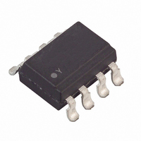
LTV-824S Lite-On Electronics, LTV-824S Datasheet - Page 14

LTV-824S
Manufacturer Part Number
LTV-824S
Description
OPTOISOLATOR 2CH AC-IN SMD
Manufacturer
Lite-On Electronics
Specifications of LTV-824S
Maximum Fall Time
18 us
Maximum Input Diode Current
50 mA
Maximum Rise Time
18 us
Output Device
Transistor
Output Type
Transistor
Configuration
2
Input Type
AC, DC
Maximum Collector Emitter Voltage
35 V
Maximum Collector Emitter Saturation Voltage
200 mV
Isolation Voltage
5000 Vrms
Current Transfer Ratio
300 %
Maximum Forward Diode Voltage
1.4 V
Maximum Collector Current
50 mA
Maximum Power Dissipation
200 mW
Maximum Operating Temperature
+ 100 C
Minimum Operating Temperature
- 30 C
Package / Case
8-SMD
Number Of Channels
2
Voltage - Isolation
5000Vrms
Current Transfer Ratio (min)
20% @ 1mA
Current Transfer Ratio (max)
300% @ 1mA
Voltage - Output
35V
Current - Output / Channel
50mA
Current - Dc Forward (if)
±50mA
Vce Saturation (max)
200mV
Mounting Type
Surface Mount
Number Of Elements
2
Forward Voltage
1.4V
Forward Current
50mA
Collector-emitter Voltage
35V
Package Type
PDIP SMD
Collector Current (dc) (max)
50mA
Power Dissipation
200mW
Collector-emitter Saturation Voltage
0.2V
Fall Time
18000ns
Rise Time
18000ns
Pin Count
8
Mounting
Surface Mount
Operating Temp Range
-30C to 100C
Operating Temperature Classification
Commercial
Lead Free Status / RoHS Status
Lead free / RoHS Compliant
Lead Free Status / RoHS Status
Lead free / RoHS Compliant, Lead free / RoHS Compliant
Other names
160-1347-5
LTV824S
LTV824S
BNS-OD-C131/A4
Part No. : LTV-814 824 844 (M, S, S-TA, S-TA1, S-TP) Series
CHARACTERISTICS CURVES
Fig.7 Relative Current Transfer Ratio
Fig.9 Collector Dark Current vs.
Fig.11 Frequency Response
vs. Ambient Temperature
Ambient Temperature
150
100
10
10
10
10
10
10
10
50
10
20
-10
-11
-5
-6
-7
-8
-9
0
0
-30
-25
0.5
V = 20V
1
L IT E - O N T E CH NO L O G Y CO RP O RAT IO N
CE
Ambient temperature Ta ( C)
Ambient temperature Ta ( C)
2
0
0
Frequency f (kHz)
5
25
25
10
R = 10k
20
L
50
50
50
100
V = 2V
Ic= 2mA
Ta= 25 C
1k
75
75
Property of LITE-ON Only
CE
o
o
100
I = 5mA
V = 5V
F
CE
o
100
100
500
125
125
Fig.8 Collector-emitter Saturation Voltage
Fig.10 Response Time vs. Load
Test Circuit for Response Time
Test Circuit for Frequency Response
vs. Ambient Temperature
0.16
0.14
0.10
0.08
0.06
0.04
Resistance
0.12
0.02
500
200
100
0.5
0.2
50
20
10
0
5
2
1
0.05
-25
V = 2V
Ic= 2mA
Ta= 25 C
CE
Ambient temperature Ta ( C)
0.1 0.2
0
Load resistance R (k )
o
25
0.5
50
ts
1
td
tr
tf
L
I = 20mA
Ic= 1mA
2
F
75
o
5
100
10
125
Page : 14 of 16


