4N25M Lite-On Electronics, 4N25M Datasheet - Page 9
4N25M
Manufacturer Part Number
4N25M
Description
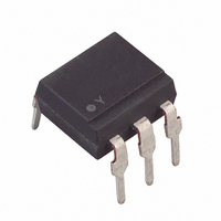
OPTOISOLATOR W/BASE 6-DIP
Manufacturer
Lite-On Electronics
Datasheet
1.4N25M.pdf
(10 pages)
Specifications of 4N25M
Output Type
Transistor with Base
Input Type
DC
Package / Case
6-DIP
Number Of Channels
1
Voltage - Isolation
2500Vrms
Current Transfer Ratio (min)
20% @ 10mA
Voltage - Output
30V
Current - Output / Channel
100mA
Current - Dc Forward (if)
80mA
Vce Saturation (max)
500mV
Mounting Type
Through Hole
Maximum Input Diode Current
80 mA
Maximum Reverse Diode Voltage
6 V
Output Device
Phototransistor
Configuration
1 Channel
Maximum Collector Emitter Voltage
30 V
Maximum Collector Emitter Saturation Voltage
0.5 V
Isolation Voltage
2500 Vrms
Maximum Forward Diode Voltage
1.5 V
Maximum Collector Current
100 mA
Maximum Power Dissipation
250 mW
Maximum Operating Temperature
+ 100 C
Minimum Operating Temperature
- 55 C
Lead Free Status / RoHS Status
Lead free / RoHS Compliant
Current Transfer Ratio (max)
-
Lead Free Status / RoHS Status
Lead free / RoHS Compliant, Lead free / RoHS Compliant
Other names
4N25MLT
Available stocks
Company
Part Number
Manufacturer
Quantity
Price

Part Number:
4N25M
Manufacturer:
FAIRCHILD/仙童
Quantity:
20 000
Part Number:
4N25M/CT4N25
Manufacturer:
FAIRCHILD/仙童
Quantity:
20 000


Fig.7 Collector-emitter Saturation Voltage vs.
Fig.9 Response Time vs. Load Resistance
Fig.11 Collector-emitter Saturation
Ambient Temperature
100
Voltage vs. Forward Current
0.1
0.1
0.3
0.2
0.5
0.2
50
20
10
1
1
0
-55
5
2
7
6
5
4
3
2
0
0.05
0
V = 10V
Ic= 2mA
Ta= 25 C
I
I
F
C
= 50mA
= 2mA
0.1
Ambient temperature Ta ( C)
-25
5
Load resistance R
Forward current I
O
0.2
10
0.5
0
1
15
25
2
20
50
F
5
L
(mA)
tf
(k )
ts
td
Ta= 25 C
10
tr
25
75
O
20 50
O
100
30
Test Circuit for Response Time
Test Circuit for Frequency Response
Fig.8 Collector Dark Current vs.
Fig.10 Frequency Response
Input
Ambient Temperature
R
D
10
10
10
10
10
10
10
10
-10
-20
-15
-10
-12
-13
-5
-7
-8
-9
-6
5
0
-55
0.5 1 2
5
5
5
5
5
5
5
V = 10V
-25
Ambient temperature Ta ( C)
R
R
R = 10k
D
L
Vcc
Frequency f (kHz)
L
0
5 10 20
Output
20
Output
Input
R
40
Vcc
L
50 100
1k
td
60
V = 5V
Ic= 2mA
Ta= 25 C
tr
Output
100
O
200 500
100
O
ts
125
tf
10%
90%
Related parts for 4N25M
Image
Part Number
Description
Manufacturer
Datasheet
Request
R

Part Number:
Description:
OPTOISOLATOR W/BASE 6-DIP
Manufacturer:
Lite-On Electronics
Datasheet:

Part Number:
Description:
Photodiodes Phototrans Filtered
Manufacturer:
Lite-On Electronics
Datasheet:

Part Number:
Description:
ENCODER/DECODER 3/16 8-SOIC
Manufacturer:
Lite-On Electronics
Datasheet:

Part Number:
Description:
OPTOCOUPLER HS LOGIC OUT 8-DIP
Manufacturer:
Lite-On Electronics
Datasheet:

Part Number:
Description:
OPTOCOUPLER HS TRANS OUT 8-DIP
Manufacturer:
Lite-On Electronics
Datasheet:

Part Number:
Description:
OPTOCOUPLER HS TRANS OUT 8-SMD
Manufacturer:
Lite-On Electronics
Datasheet:

Part Number:
Description:
OPTOCOUPLER HS TRANS OUT 8-DIP
Manufacturer:
Lite-On Electronics
Datasheet:

Part Number:
Description:
OPTOCOUPLER HS LOGIC OUT 8-SMD
Manufacturer:
Lite-On Electronics
Datasheet:

Part Number:
Description:
OPTOCOUPLER HS TRANS OUT 8-SMD
Manufacturer:
Lite-On Electronics
Datasheet:

Part Number:
Description:
OPTOISOLATOR 1CH 4-DIP
Manufacturer:
Lite-On Electronics
Datasheet:
Part Number:
Description:
OPTOISOLATOR W/BASE 6-DIP
Manufacturer:
Lite-On Electronics
Datasheet:
Part Number:
Description:
OPTOISOLATOR W/BASE 6-DIP
Manufacturer:
Lite-On Electronics
Datasheet:
Part Number:
Description:
OPTOISOLATOR W/BASE 6-DIP
Manufacturer:
Lite-On Electronics
Datasheet:
Part Number:
Description:
OPTOISOLATOR W/O BASE 6-DIP
Manufacturer:
Lite-On Electronics
Datasheet:
Part Number:
Description:
OPTOISOLATOR W/O BASE 6-DIP
Manufacturer:
Lite-On Electronics
Datasheet: