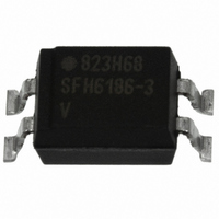
SFH6106-2T Vishay, SFH6106-2T Datasheet - Page 6

SFH6106-2T
Manufacturer Part Number
SFH6106-2T
Description
OPTOCOUPLER PHOTOTRANS 125% 4SMD
Manufacturer
Vishay
Datasheet
1.SFH610A-2.pdf
(10 pages)
Specifications of SFH6106-2T
Number Of Channels
1
Input Type
DC
Voltage - Isolation
5300Vrms
Current Transfer Ratio (min)
22% @ 1mA
Current Transfer Ratio (max)
125% @ 10mA
Voltage - Output
70V
Current - Output / Channel
50mA
Current - Dc Forward (if)
60mA
Vce Saturation (max)
400mV
Output Type
Transistor
Mounting Type
Surface Mount
Package / Case
4-SMD (300 mil)
Maximum Input Diode Current
60 mA
Maximum Reverse Diode Voltage
6 V
Output Device
Transistor
Configuration
1
Maximum Collector Emitter Voltage
70 V
Maximum Collector Emitter Saturation Voltage
400 mV
Isolation Voltage
5300 Vrms
Current Transfer Ratio
125 %
Maximum Forward Diode Voltage
1.65 V
Maximum Collector Current
100 mA
Maximum Power Dissipation
150 mW
Maximum Operating Temperature
+ 100 C
Minimum Operating Temperature
- 55 C
Lead Free Status / RoHS Status
Lead free / RoHS Compliant
Lead Free Status / RoHS Status
Lead free / RoHS Compliant, Lead free / RoHS Compliant
Available stocks
Company
Part Number
Manufacturer
Quantity
Price
Company:
Part Number:
SFH6106-2T
Manufacturer:
TI
Quantity:
18 720
Part Number:
SFH6106-2T
Manufacturer:
VISHAY/威世
Quantity:
20 000
SFH610A, SFH6106
Vishay Semiconductors
www.vishay.com
612
Fig. 6 - Transistor Capacitance (Typ.) vs. Collector Emitter Voltage
Fig. 7 - Permissible Pulse Handling Capability Forward Current vs.
Fig. 5 - Diode Forward Voltage vs. Forward Current
isfh610a_05
isfh610a_06
isfh610a_07
V
I
F
F
C
10
10
10
10
mA
1.2
1.1
1.0
0.9
pF
20
15
10
V
5
5
0
4
3
2
1
5
5
10
10
10
0.05
0.1
0.2
0.5
DC
-1
-5
-2
D = 0
10
0.005
0.01
0.02
-4
5
10
Pulse Width
-1
D =
10
10
-3
0
f = 1.0 MHz
t p
T
V F = f (I F )
10
10
D = parameter
For technical questions, contact: optocoupler.answers@vishay.com
Pulse cycle
0
-2
5
t p
t p
C
CE
10
V
10
e
T
1
10
-1
1
Optocoupler, Phototransistor Output,
I
25 °C
50 °C
75 °C
t
5 mA
F
p
10
0
V
s
I
I
F
F
10
10
10
High Reliability, 5300 V
1
2
2
Fig. 8 - Permissible Power Dissipation vs. Temperature
P
isfh610a_09
isfh610a_08
Fig. 9 - Permissible Diode Forward Current vs.
tot
I
F
200
mW
150
100
120
RMS
mA
50
90
60
30
0
0
0
0
Ambient Temperature
25
25
P tot = f (T A )
Diode
Transistor
50
50
Document Number: 83666
75
75
Rev. 2.0, 10-Dec-08
T
T
A
A
°C
°C
100
100


