IL221AT Vishay, IL221AT Datasheet
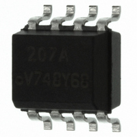
OPTOCOUPLER PHOTODARL 100% 8SOIC

IL221AT

Manufacturer Part Number
IL221AT
Description
OPTOCOUPLER PHOTODARL 100% 8SOIC
Manufacturer
Vishay
Datasheet

Specifications of IL221AT

Mounting Type
Surface Mount
Isolation Voltage
4000 Vrms
Number Of Channels
1
Input Type
DC
Voltage - Isolation
4000Vrms
Current Transfer Ratio (min)
100% @ 1mA
Voltage - Output
30V
Current - Dc Forward (if)
60mA
Vce Saturation (max)
1V
Output Type
Darlington with Base
Package / Case
8-SOIC (3.9mm Width)
Maximum Input Diode Current
60 mA
Maximum Reverse Diode Voltage
6 V
Output Device
Photodarlington
Configuration
1 Channel
Maximum Collector Emitter Voltage
30 V
Maximum Collector Emitter Saturation Voltage
1 V
Maximum Forward Diode Voltage
1.5 V
Maximum Collector Current
100 mA
Maximum Power Dissipation
240 mW
Maximum Operating Temperature
+ 100 C
Minimum Operating Temperature
- 55 C
No. Of Channels
1
Optocoupler Output Type
Photodarlington
Input Current
1mA
Output Voltage
30V
Opto Case Style
SOIC
No. Of Pins
8
Lead Free Status / RoHS Status
Lead free / RoHS Compliant
Current - Output / Channel
-
Current Transfer Ratio (max)
-
Lead Free Status / RoHS Status
Lead free / RoHS Compliant, Lead free / RoHS Compliant
IL221AT/222AT/223AT
Vishay Semiconductors
DESCRIPTION
The IL221AT/IL222AT/IL223AT is a high current transfer
ratio (CTR) optocoupler with a gallium arsenide infrared LED
emitter and a silicon NPN photodarlington transistor
detector.
The device has a CTR tested at 1.0 mA LED current. This
low drive current permits easy interfacing from CMOS to
LSTTL or TTL.
This optocoupler is constructed in a standard SOIC-8 foot
print which makes it ideally suited for high density
applications.
requirements, this package conforms to standards for
surface mount devices.
www.vishay.com
330
ORDER INFORMATION
PART
IL221AT
IL222AT
IL223AT
ABSOLUTE MAXIMUM RATINGS
PARAMETER
INPUT
Peak reverse voltage
Forward continuous current
Power dissipation
Derate linearly from 25 °C
OUTPUT
Collector emitter breakdown voltage
Emitter collector breakdown voltage
Collector base breakdown voltage
I
I
Power dissipation
Derate linearly from 25 °C
CMAX DC
CMAX
i179022
Low Input Current, High Gain, with Base Connection
In
addition
Optocoupler, Photodarlington Output,
to
NC
NC
For technical questions, contact: optocoupler.answers@vishay.com
C
A
eliminating
1
2
3
4
through-hole
TEST CONDITION
8
6
7
5
NC
B
C
E
t < 1.0 ms
FEATURES
• Isolation test voltage, 4000 V
• Industry standard SOIC-8 surface mountable
• Standard lead spacing, 0.05"
• Available only on tape and reel (conforms to
• Compatible with dual wave, vapor phase and IR reflow
• Lead (Pb)-free component
• Component in accordance to RoHS 2002/95/EC and
AGENCY APPROVALS
• UL1577, file no. E52744 system code Y
• CUL - file no. E52744, equivalent to CSA bulletin 5A
• DIN EN 60747-5-5 available with option 1
package
EIA standard RS481A)
soldering
WEEE 2002/96/EC
SYMBOL
I
CMAX DC
BV
BV
BV
I
P
P
CMAX
V
I
diss
diss
CEO
ECO
CBO
F
R
CTR > 100 %, SOIC-8
CTR > 200 %, SOIC-8
CTR > 500 %, SOIC-8
REMARKS
VALUE
100
150
6.0
1.2
5.0
2.0
60
90
30
70
50
RMS
Document Number: 83617
Rev. 1.8, 08-May-08
mW/°C
mW/°C
UNIT
mW
mW
mW
mA
mA
V
V
V
V

Related parts for IL221AT

IL221AT Summary of contents

Page 1

... i179022 DESCRIPTION The IL221AT/IL222AT/IL223AT is a high current transfer ratio (CTR) optocoupler with a gallium arsenide infrared LED emitter and a silicon NPN photodarlington transistor detector. The device has a CTR tested at 1.0 mA LED current. This low drive current permits easy interfacing from CMOS to LSTTL or TTL. ...

Page 2

... 100 µ µ 0 TEST CONDITION PART SYMBOL IL221AT CTR I = 1.0 mA 5.0 V IL222AT CTR F CE IL223AT CTR TEST CONDITION SYMBOL CTI IL221AT/222AT/223AT Vishay Semiconductors VALUE V 4000 ISO P 240 tot 3 150 stg 100 amb 10 MIN. TYP. MAX. V 1.0 1 0.1 100 CEO 5.0 ...

Page 3

... mA ° ° ° ° 0 LED Current (mA) I iil221at_03 F Fig Normalized CTR vs 100 ° ° ° ° Normalized to mA °C A 0.1 0 LED Current (mA) F iil221at_04 Fig Normalized CTR vs. LED Current CE Document Number: 83617 Rev. 1.8, 08-May-08 UNIT ° 100 100 ...

Page 4

... IL221AT/222AT/223AT Vishay Semiconductors 100 ° ° ° ° 0.1 0 LED Current (mA) F iil221at_08 Fig Photocurrent vs. LED Current 1000 °C Normalized to ° °C 100 ° 0.1 0 LED Current (mA) iil221at_09 F Fig Normalized I vs PLH PHL iil221at_10 Fig Switching Timing www.vishay.com 100 333 ...

Page 5

... IL221AT/222AT/223AT Vishay Semiconductors kHz iil221at_11 Fig Switching Schematic PACKAGE DIMENSIONS in inches (millimeters) 0.120 ± 0.005 (3.05 ± 0.13) 0.240 (6.10) Pin one ID 0.192 ± 0.005 (4.88 ± 0.13) 0.004 (0.10) 0.008 (0.20) ISO method A i178003 www.vishay.com For technical questions, contact: optocoupler.answers@vishay.com ...

Page 6

... Vishay Semiconductor GmbH, P.O.B. 3535, D-74025 Heilbronn, Germany Document Number: 83617 For technical questions, contact: optocoupler.answers@vishay.com Rev. 1.8, 08-May-08 Connection and may do so without further notice. IL221AT/222AT/223AT Vishay Semiconductors www.vishay.com 335 ...

Page 7

... Vishay product could result in personal injury or death. Customers using or selling Vishay products not expressly indicated for use in such applications their own risk and agree to fully indemnify and hold Vishay and its distributors harmless from and against any and all claims, liabilities, expenses and damages arising or resulting in connection with such use or sale, including attorneys fees, even if such claim alleges that Vishay or its distributor was negligent regarding the design or manufacture of the part ...

Related keywords