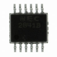
PS2841-4B-A CEL, PS2841-4B-A Datasheet - Page 4

PS2841-4B-A
Manufacturer Part Number
PS2841-4B-A
Description
PHOTOCOUPLER 4CH TRANS OUT SM
Manufacturer
CEL
Series
NEPOCr
Datasheet
1.PS2841-4B-F3-A.pdf
(12 pages)
Specifications of PS2841-4B-A
Number Of Channels
4
Input Type
DC
Voltage - Isolation
1500Vrms
Current Transfer Ratio (min)
100% @ 1mA
Current Transfer Ratio (max)
400% @ 1mA
Voltage - Output
70V
Current - Output / Channel
20mA
Current - Dc Forward (if)
20mA
Vce Saturation (max)
300mV
Output Type
Transistor
Mounting Type
Surface Mount
Package / Case
12-SMD
Maximum Fall Time
110 us
Maximum Input Diode Current
20 mA
Maximum Reverse Diode Voltage
6 V
Maximum Rise Time
20 us
Maximum Collector Emitter Voltage
70 V
Maximum Collector Emitter Saturation Voltage
0.3 V
Isolation Voltage
1500 Vrms
Current Transfer Ratio
400 %
Maximum Forward Diode Voltage
1.2 V
Maximum Collector Current
20 mA
Maximum Power Dissipation
40 mW
Maximum Operating Temperature
+ 100 C
Minimum Operating Temperature
- 40 C
Lead Free Status / RoHS Status
Lead free / RoHS Compliant
Other names
PS2841-4B
ELECTRICAL CHARACTERISTICS (T
4
Diode
Transistor
Coupled
*1 The optically induced leakage current is current which can be measured at transistor if LED = ”ON” and LED =
*2 Test circuit for switching time
”OFF”.
LED of channel 1 is switched to ”ON”.
At Tr-output of channel 2 a voltage is applied and one can measure a current between emitter and collector.
This is leakage current (at I
Measurement circuits for optical leakage current
E.g. : In the case of 1 to 2-ch (PS2841-4A)
Pulse Input
PW = 100 s
Duty cycle = 1/10
In monitor
I
F
Forward Voltage
Reverse Current
Terminal Capacitance
Collector to Emitter Current
Current Transfer Ratio (I
Optical Leakage Current
(1 to 2-ch, 2 to 3-ch, 3 to 4-ch)
Collector Saturation Voltage
Isolation Resistance
Isolation Capacitance
Turn-on Time
Turn-off Time
Parameter
1
2
3
4
5
6
µ
*2
*2
I
F
50 Ω
F
C
*1
/I
= 5 mA, V
F
)
12
11
10
9
8
7
Symbol
V
CTR
I
CE (sat)
R
C
V
CEO
C
t
t
I
I
on
off
R
I-O
I-O
A
L
CEO
F
t
R
Data Sheet PN10202EJ04V0DS
= 25°C)
A
I
L
L
= 5 kΩ
= 24 V).
I
V
V = 0 V, f = 1 MHz
I
I
I
I
V
V = 0 V, f = 1 MHz
V
F
F
F
F
F
R
I-O
CC
= 1 mA
= 0 mA, V
= 1 mA, V
= 5 mA, V
= 1 mA, I
= 5 V
= 1 kV
= 5 V, I
V
V
CC
OUT
DC
C
F
CE
CE
CE
Conditions
= 0.2 mA
= 1 mA, R
= 24 V
= 0.4 V
= 24 V
L
= 5 kΩ
PS2841-4A,PS2841-4B
MIN.
100
10
0.9
11
TYP.
0.13
200
110
1.1
0.4
15
20
MAX.
100
400
100
1.2
0.3
10
Unit
µ
pF
nA
nA
pF
µ
%
V
V
Ω
A
s


