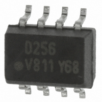
ILD256T Vishay, ILD256T Datasheet - Page 4

ILD256T
Manufacturer Part Number
ILD256T
Description
OPTOCOUPLER PHOTOTRANS 2CH 8SOIC
Manufacturer
Vishay
Datasheet
1.ILD256T.pdf
(7 pages)
Specifications of ILD256T
Mounting Type
Surface Mount
Isolation Voltage
4000 Vrms
Number Of Channels
2
Input Type
AC, DC
Voltage - Isolation
4000Vrms
Current Transfer Ratio (min)
20% @ 10mA
Voltage - Output
70V
Current - Dc Forward (if)
30mA
Vce Saturation (max)
400mV
Output Type
Transistor
Package / Case
8-SOIC (3.9mm Width)
Forward Current
30 mA
Maximum Input Diode Current
30 mA
Output Device
Transistor
Configuration
2
Maximum Collector Emitter Voltage
70 V
Maximum Collector Emitter Saturation Voltage
400 mV
Maximum Forward Diode Voltage
1.55 V
Maximum Power Dissipation
300 mW
Maximum Operating Temperature
+ 100 C
Minimum Operating Temperature
- 55 C
No. Of Channels
2
Optocoupler Output Type
Phototransistor
Input Current
10mA
Output Voltage
70V
Opto Case Style
SOIC
No. Of Pins
8
Lead Free Status / RoHS Status
Lead free / RoHS Compliant
Current - Output / Channel
-
Current Transfer Ratio (max)
-
Lead Free Status / Rohs Status
Lead free / RoHS Compliant
Other names
751-1317-2
ILD256TGITR
ILD256TGITR
ILD256TGITR
ILD256TGITR
Available stocks
Company
Part Number
Manufacturer
Quantity
Price
Company:
Part Number:
ILD256T
Manufacturer:
PHILIPS
Quantity:
6 222
ILD256T
Vishay Semiconductors
www.vishay.com
4
iil256at_07
iil256at_08
iil256at_09
Figure 9. Normalized HFE vs. Base Current and Temp.
1000
700
600
500
400
300
200
100
100
1.2
1.0
0.8
0.6
0.4
0.1
10
1
0.1
1
1
NHFE - 20 °C
NHFE 25 °C
NHFE 50 °C
NHFE 70 °C
Figure 7. Photocurrent vs. LED Current
V
Figure 8. Base Current vs. I
CE
= 0.4 V
I
B
I
F
I
- Base Current (µA)
B
10
- LED Current (mA)
1
10
- Base Current (µA)
For technical support, please contact: optocoupler.answers@vishay.com
100
100
10
F
Normalized to:
I
V
and HFE
B
CE
= 10 µA
= 10
25 °C
70 °C
1000
1000
100
100
10
1
0.1
iil256at_12
iil256at_11
iil256at_10
Figure 10. Normalized Saturated HFE vs. Base Current
Figure 12. Collector-Emitter Leakage Current vs.Temp.
0.001
1000
10
10
0.01
10
10
10
10
10
10
1.5
1.0
0.5
0.0
100
Figure 11. Base Emitter Voltage vs. Base Current
0.1
10
-1
-2
5
4
3
2
1
0
1
- 20
0.4
1
T
0
A
- Ambient Temperature (°C)
V
0.5
BE
I
Normalized to:
HFE at V
I
- Base Emitter Voltage (V)
B
CB
10
20
- Base Current (µA)
= 10 µA
0.6
T ypical
CE
40
= 10 V
100
V
Document Number 83649
60
CE(sat)
T
T
T
T
V
A
A
A
A
0.7
CE
= - 20 °C
= 25 °C
= 50 °C
= 70 °C
Rev. 1.6, 20-Apr-07
= 0.4 V
= 10 V
80
1000
0.8
100


