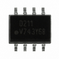
ILD211T Vishay, ILD211T Datasheet - Page 4

ILD211T
Manufacturer Part Number
ILD211T
Description
OPTOCOUPLER PHOTO DUAL 20% 8SOIC
Manufacturer
Vishay
Specifications of ILD211T
Mounting Type
Surface Mount
Isolation Voltage
4000 Vrms
Number Of Channels
2
Input Type
DC
Voltage - Isolation
4000Vrms
Current Transfer Ratio (min)
20% @ 10mA
Voltage - Output
70V
Vce Saturation (max)
400mV
Output Type
Transistor
Package / Case
8-SOIC (3.9mm Width)
Forward Current
30 mA
Maximum Input Diode Current
30 mA
Maximum Reverse Diode Voltage
6 V
Output Device
Transistor
Configuration
2
Maximum Collector Emitter Voltage
70 V
Maximum Collector Emitter Saturation Voltage
400 mV
Maximum Forward Diode Voltage
1.55 V
Maximum Power Dissipation
300 mW
Maximum Operating Temperature
+ 100 C
Minimum Operating Temperature
- 55 C
No. Of Channels
2
Optocoupler Output Type
Phototransistor
Input Current
10mA
Output Voltage
70V
Opto Case Style
SOIC
No. Of Pins
8
Lead Free Status / RoHS Status
Lead free / RoHS Compliant
Current - Output / Channel
-
Current - Dc Forward (if)
-
Current Transfer Ratio (max)
-
Lead Free Status / Rohs Status
Lead free / RoHS Compliant
Other names
751-1311-2
ILD211TGITR
ILD211TGITR
ILD211TGITR
ILD211TGITR
Available stocks
Company
Part Number
Manufacturer
Quantity
Price
Company:
Part Number:
ILD211T
Manufacturer:
INFINEON
Quantity:
3 164
Company:
Part Number:
ILD211T
Manufacturer:
SIEMENS
Quantity:
3 169
Part Number:
ILD211T
Manufacturer:
VISHAY/威世
Quantity:
20 000
ILD205T/206T/207T/211T/213T/217T
Vishay Semiconductors
TYPICAL CHARACTERISTICS
T
www.vishay.com
4
amb
iild205t_02
iild205t_03
= 25 °C, unless otherwise specified
iild205t_01
1.2
1.0
0.8
0.6
0.4
0.2
0.0
1.2
1.0
0.8
0.6
0.4
0.2
0.0
Fig. 3 - Normalized CTR
Fig. 1 - Forward Current vs. Forward Voltage
Fig. 2 - Collector Emitter Current vs. V
0.01
0
30
25
20
15
10
Coll Current Normalized at I = 10 mA
V
5
0
0.6
CTR normalized at
I
CE
F
V
CE
= 10 mA
= 10 V
2
V
- Collector To Emitter Voltage (V)
f
0.1
I
- LED Forward Voltage (V)
F
0.8
- LED Current (mA)
4
85 °C
60 °C
25 °C
CE
1.0
6
1
vs. Forward Current
For technical questions, contact: optocoupler.answers@vishay.com
8
F
Optocoupler, Phototransistor Output,
1.2
V
CE
10
Dual Channel, SOIC-8 package
I
I
I
F
F
F
V
= 0.4 V
CE
CE
= 10 mA
10
= 5 mA
= 1 mA
= 5 V
1.4
100
12
iild205t_04
iild205t_05
Fig. 6 - Collector Current vs. Ambient Temperature
Fig. 4 - Current Transfer Ratio (normalized) vs.
10
10
10
10
iild205t_06
1.2
1.0
0.8
0.6
0.4
0.2
0.0
Fig. 5 - Switching Speed vs. Load Resistor
0.001
3
2
1
0
0.01
0.1
20
0.1
1
I
I
I
F
F
I
Pulse Width = 100 ms
Duty Cycle = 50 %
F
20
F
= 5 mA
= 1 mA
= 10 mA
= 10 mA
Ambient Temperature
40
RI - Load Resistor (kΩ)
40
T
Ta - Temperature (°C)
A
1
- Temperature (°C)
CTR nonsat normalized at
V
60
V
60
CE
CE
= 10 V
= 50 V
Document Number: 83647
10
80
Rev. 1.7, 19-Nov-07
V
I
80
F
CE
= 10 mA
t
off
t
= 10 V
on
100
100
100


