IL213AT Vishay, IL213AT Datasheet - Page 3
IL213AT
Manufacturer Part Number
IL213AT
Description
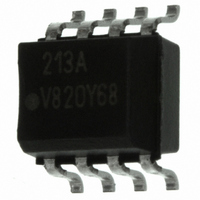
OPTOCOUPLER PHOTOTRNS 100% 8SOIC
Manufacturer
Vishay
Specifications of IL213AT
Mounting Type
Surface Mount
Isolation Voltage
4000 Vrms
Number Of Channels
1
Input Type
DC
Voltage - Isolation
4000Vrms
Current Transfer Ratio (min)
100% @ 10mA
Voltage - Output
30V
Current - Dc Forward (if)
60mA
Vce Saturation (max)
400mV
Output Type
Transistor with Base
Package / Case
8-SOIC (3.9mm Width)
Maximum Input Diode Current
60 mA
Maximum Reverse Diode Voltage
6 V
Output Device
Phototransistor
Configuration
1 Channel
Maximum Collector Emitter Voltage
30 V
Maximum Collector Emitter Saturation Voltage
0.4 V
Current Transfer Ratio
130 %
Maximum Forward Diode Voltage
1.5 V
Maximum Collector Current
100 mA
Maximum Power Dissipation
240 mW
Maximum Operating Temperature
+ 100 C
Minimum Operating Temperature
- 55 C
No. Of Channels
1
Optocoupler Output Type
Phototransistor
Input Current
10mA
Output Voltage
30V
Opto Case Style
SOIC
No. Of Pins
8
Approval Bodies
UL1577, DIN EN
Rohs Compliant
Yes
Lead Free Status / RoHS Status
Lead free / RoHS Compliant
Current - Output / Channel
-
Current Transfer Ratio (max)
-
Lead Free Status / Rohs Status
Lead free / RoHS Compliant
Other names
751-1287-2
IL213ATGITR
IL213ATGITR
IL213ATGITR
IL213ATGITR
Available stocks
Company
Part Number
Manufacturer
Quantity
Price
Company:

Part Number:
IL213AT
Manufacturer:
INFINEON
Quantity:
6 210
Company:
Part Number:
IL213AT
Manufacturer:
JRC
Quantity:
6 210
Part Number:
IL213AT
Manufacturer:
VISHAY/威世
Quantity:
20 000


Note
• As per IEC 60747-5-2, § 7.4.3.8.1, this optocoupler is suitable for “Safe Electrical Insulation” only within the safety ratings. Compliance with
TYPICAL CHARACTERISTICS (T
Document Number: 83615
Rev. 1.9, 21-Dec-10
SAFETY AND INSULATION RATINGS
PARAMETER
Climatic classification
(according to IEC 68 part 1)
Comparative tracking index
V
V
P
I
T
Creepage distance
Clearance distance
Insulation thickness
SI
the safety ratings shall be ensured by means of protective circuits.
SI
IOTM
IORM
SO
Fig. 2 - Collector Current vs. Collector Emitter Voltage (NS)
22462
22463
Fig. 1 - Forward Voltage vs. Forward Current
1.8
1.6
1.4
1.2
1.0
0.8
0.6
50
45
40
35
30
25
20
15
10
5
0
0.1
0
V
T
CE
amb
- Collector Emitter Voltage (N ) (V)
1
= - 55 °C
T
amb
I
F
= 100 °C
- Forward Current (mA)
2
T
amb
1
= - 40 °C
3
T
I
amb
F
= 30 mA
I
= 75 °C
F
4
T
= 20 mA
with Base Connection in SOIC-8 Package
amb
For technical questions, contact:
T
amb
I
F
Optocoupler, Phototransistor Output,
= 50 °C
5
= 15 mA
10
= 0 °C
T
TEST CONDITION
amb
I
6
amb
F
= 10 mA
= 25 °C
I
F
= 5 mA
7
= 25 °C, unless otherwise specified)
100
8
SYMBOL
optocoupleranswers@vishay.com
CTI
Fig. 4 - Collector Current vs. Collector Emitter Voltage (sat)
Fig. 3 - Leakage Current vs. Ambient Temperature
22466
IL211AT, IL212AT, IL213AT
22464
10 000
0.001
MIN.
6000
1000
175
560
0.2
0.01
100
4
4
0.1
30
25
20
15
10
10
5
0
1
- 60 - 40 - 20
0
V
CE
T
I
F
amb
- Collector Emitter Voltage ( at) (V)
= 0 mA
55/100/21
- Ambient Temperature (°C)
Vishay Semiconductors
0.1
TYP.
V
CE
0
= 40 V
I
0.2
20
F
= 1 mA
I
V
F
40
CE
= 25 mA
MAX.
I
399
350
150
165
F
= 12 V
= 10 mA
V
I
0.3
F
60
CE
= 5 mA
I
F
= 24 V
= 2 mA
80 100
www.vishay.com
0.4
UNIT
mW
mm
mm
mm
mA
°C
V
V
3
Related parts for IL213AT
Image
Part Number
Description
Manufacturer
Datasheet
Request
R

Part Number:
Description:
357-036-542-201 CARDEDGE 36POS DL .156 BLK LOPRO
Manufacturer:
Vishay
Datasheet:
Part Number:
Description:
357-036-542-201 CARDEDGE 36POS DL .156 BLK LOPRO
Manufacturer:
Vishay
Datasheet:
Part Number:
Description:
357-036-542-201 CARDEDGE 36POS DL .156 BLK LOPRO
Manufacturer:
Vishay
Datasheet:
Part Number:
Description:
357-036-542-201 CARDEDGE 36POS DL .156 BLK LOPRO
Manufacturer:
Vishay
Datasheet:
Part Number:
Description:
357-036-542-201 CARDEDGE 36POS DL .156 BLK LOPRO
Manufacturer:
Vishay
Datasheet:
Part Number:
Description:
357-036-542-201 CARDEDGE 36POS DL .156 BLK LOPRO
Manufacturer:
Vishay
Datasheet:
Part Number:
Description:
357-036-542-201 CARDEDGE 36POS DL .156 BLK LOPRO
Manufacturer:
Vishay
Datasheet:
Part Number:
Description:
357-036-542-201 CARDEDGE 36POS DL .156 BLK LOPRO
Manufacturer:
Vishay
Datasheet:
Part Number:
Description:
357-036-542-201 CARDEDGE 36POS DL .156 BLK LOPRO
Manufacturer:
Vishay
Datasheet:
Part Number:
Description:
357-036-542-201 CARDEDGE 36POS DL .156 BLK LOPRO
Manufacturer:
Vishay
Datasheet:
Part Number:
Description:
357-036-542-201 CARDEDGE 36POS DL .156 BLK LOPRO
Manufacturer:
Vishay
Datasheet:
Part Number:
Description:
357-036-542-201 CARDEDGE 36POS DL .156 BLK LOPRO
Manufacturer:
Vishay
Datasheet:
Part Number:
Description:
357-036-542-201 CARDEDGE 36POS DL .156 BLK LOPRO
Manufacturer:
Vishay
Datasheet:
Part Number:
Description:
357-036-542-201 CARDEDGE 36POS DL .156 BLK LOPRO
Manufacturer:
Vishay
Datasheet:
Part Number:
Description:
357-036-542-201 CARDEDGE 36POS DL .156 BLK LOPRO
Manufacturer:
Vishay
Datasheet: