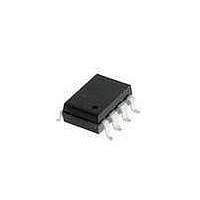
HCPL-3100-500E Avago Technologies US Inc., HCPL-3100-500E Datasheet - Page 4

HCPL-3100-500E
Manufacturer Part Number
HCPL-3100-500E
Description
OPTOCOUPLER GATE DRIVER 8-SMD
Manufacturer
Avago Technologies US Inc.
Datasheet
1.HCPL-3100.pdf
(14 pages)
Specifications of HCPL-3100-500E
Package / Case
8-SMD Gull Wing
Voltage - Isolation
5000Vrms
Number Of Channels
1, Unidirectional
Current - Output / Channel
100mA
Propagation Delay High - Low @ If
2µs @ 10mA
Current - Dc Forward (if)
20mA
Input Type
DC
Output Type
Push-Pull, Totem-Pole
Mounting Type
Surface Mount, Gull Wing
Isolation Voltage
5000 Vrms
Maximum Continuous Output Current
100 mA
Maximum Fall Time
0.5 us
Maximum Forward Diode Current
25 mA
Maximum Rise Time
0.5 us
Output Device
Integrated Photo IC
Configuration
1 Channel
Maximum Forward Diode Voltage
1.4 V
Maximum Reverse Diode Voltage
6 V
Maximum Power Dissipation
550 mW
Maximum Operating Temperature
+ 70 C
Minimum Operating Temperature
- 40 C
Number Of Elements
1
Forward Voltage
1.4V
Forward Current
25mA
Output Current
100mA
Package Type
PDIP SMD
Operating Temp Range
-40C to 100C
Fall Time
500ns
Rise Time
500ns
Power Dissipation
550mW
Propagation Delay Time
2000ns
Pin Count
8
Mounting
Surface Mount
Reverse Breakdown Voltage
6V
Operating Temperature Classification
Industrial
Lead Free Status / RoHS Status
Lead free / RoHS Compliant
Lead Free Status / RoHS Status
Lead free / RoHS Compliant, Lead free / RoHS Compliant
Demonstrated ESD
Performance
Human Body Model: MIL-STD-
Machine Model: EIAJ IC-121-
4
Insulation and Safety Related Specifications
Min. External Air Gap
(External Clearance)
Min. External Tracking
Path (External
Creepage)
Min. Internal Plastic
Gap (Internal
Clearance)
Absolute Maximum Ratings
Storage Temperature
Operating Temperature
Input
Supply Voltage V
Output 1
Output 2
Output Power Dissipation
Total Power Dissipation
Lead Solder Temperature
883 Method 3015.7: Class 2
1988 (1988.3.28 Version 2),
Test Method 20, Condition
C: 1200 V
Parameter
Parameter
Continuous
Current
Reverse
Voltage
Continuous
Current
Peak Current
Voltage
Continuous
Current
Peak Current
CC
Symbol
L(IO1)
L(IO2)
Symbol
V
I
I
T
T
V
P
P
I
O1
O2
O1
A
F
O
S
R
T
Regulatory Information
The HCPL-3100/3101 has been
approved by the following
organization:
UL
Recognized under UL 1577,
Component Recognition
Program, File E55361.
Value
0.15
6.0
6.0
HCPL-3100
HCPL-3101
HCPL-3100
HCPL-3101
HCPL-3100
HCPL-3101
Device
270 C for 10 s, 1.0 mm below seating plane
Units
mm
mm
mm
Min.
-55
-40
-40
35
Shortest distance measured through air, between two
conductive leads, input to output
Shortest distance path measured along outside surface
of optocoupler body between input and output leads
Through insulation distance conductor to conductor
inside the optocoupler cavity
Max.
125
100
500
550
0.1
0.6
0.1
0.6
85
25
20
35
V
6
5
Unit
mW
mW
mA
mA
V
A
A
V
A
A
C
C
T
Pulse Width < 0.15 s,
Duty cycle = 1%
Pulse Width < 0.15 s,
Duty cycle = 1%
A
Conditions
= 25 C
Conditions
Fig.
11
11
12
12
Note
1
1
1
1
1
1
1
1


