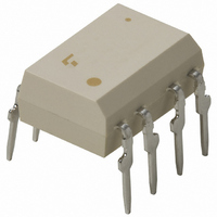
TLP351(F) Toshiba, TLP351(F) Datasheet - Page 58

TLP351(F)
Manufacturer Part Number
TLP351(F)
Description
IC PHOTOCOUPLER IRED 8-DIP
Manufacturer
Toshiba
Specifications of TLP351(F)
Voltage - Isolation
3750Vrms
Number Of Channels
1, Unidirectional
Current - Output / Channel
600mA
Current - Dc Forward (if)
20mA
Input Type
DC
Output Type
Push-Pull, Totem-Pole
Mounting Type
Through Hole
Package / Case
8-DIP (0.300", 7.62mm)
Configuration
1 Channel
Maximum Forward Diode Voltage
1.7 V
Maximum Reverse Diode Voltage
5 V
Maximum Input Diode Current
10 mA
Maximum Operating Temperature
+ 100 C
Minimum Operating Temperature
- 40 C
Isolation Voltage
3750 Vrms
Maximum Continuous Output Current
0.6 A
Maximum Fall Time
50 ns
Maximum Forward Diode Current
20 mA
Maximum Rise Time
50 ns
Minimum Forward Diode Voltage
1.55 V
Output Device
Totem Pole
No. Of Channels
1
Optocoupler Output Type
Gate Drive
Input Current
10mA
Output Voltage
35V
Opto Case Style
DIP
No. Of Pins
8
Operating Temperature Range
-40°C To
Rohs Compliant
Yes
Lead Free Status / RoHS Status
Lead free / RoHS Compliant
Other names
TLP351
TLP351
TLP351F
TLP351
TLP351F
Available stocks
Company
Part Number
Manufacturer
Quantity
Price
Company:
Part Number:
TLP351(F)
Manufacturer:
TOSHIBA
Quantity:
28 000
Part Number:
TLP351(F)
Manufacturer:
TOSHIBA/东芝
Quantity:
20 000
9
Toshiba photocouplers use one of four types of LEDs and a projection of the operating life has been made for each LED. The table on
page 57 shows the types of LED used in photocouplers and the figures on pages 58 to 60 show projections of long-term light output
performance and operating life. Note that these operating life data are estimates extrapolated from long-term light output degradation
over a single wafer lot and are shown as reference only.
F50% (cumulative failure rate 50%) operating life: Time period until the projected long-term light output degradation curve of
F0.1% (cumulative failure rate 0.1%) operating life: Time period until the projected long-term light output degradation curve of
The relationship between LED light output degradation and optical coupling characteristics is shown below.
(1) The relationship between LED light output degradation
(2) The relationship between a reciprocal value of LED light output degradation
1
1
2
3
4
and current transfer ratio (CTR)/short circuit current (I
and I
GaAs LED
GaA As ( SH ) LED
GaA As ( DH ) LED
GaA As ( MQW ) LED
Device Degradation
Projected Operating Life Based on LED Light Output Degradation
FT
/I
FLH
/I
FHL
/I
FH
change is 1:1.
F50% operating life
1,300,000 h
1,000,000 h
Ask your local Toshiba sales representative.
540,000 h
Ta = 40°C, I
degradation rate Δ P
Projected Operating Life
the average light output change (X ) shown on pages 58 to 60 reaches the
failure criteria.
X - 3σ shown on pages 58 to 60 reaches the failure criteria.
F
= 20 mA, failure criteria:
CTR (t)
CTR (o)
I
I
FT
FT
SC
(t)
(o)
) is 1:1.
O
F0.1% operating life
< –50%
58
=
=
260,000 h
100,000 h
200,000 h
(
Po (t )
Po (o)
Po ( t)
Po (o)
)
-1
Mainly for phototransistor output devices
and phototriac output devices
Mainly for photo-IC couplers
Mainly for photorelays (MOSFET output),
photovoltaic couplers and photo-IC couplers
Mainly for photo-IC couplers
Photocouplers


