5962-9314001HXA Avago Technologies US Inc., 5962-9314001HXA Datasheet - Page 2
5962-9314001HXA
Manufacturer Part Number
5962-9314001HXA
Description
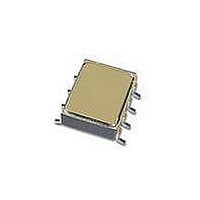
OPTOCOUPLER MOSFET HERM 8DIP
Manufacturer
Avago Technologies US Inc.
Datasheet
1.HSSR-7110600.pdf
(11 pages)
Specifications of 5962-9314001HXA
Package / Case
8-SMD Gull Wing
Output Type
Gate Driver
Voltage - Isolation
1500VDC
Number Of Channels
1, Unidirectional
Current - Output / Channel
1.6A
Current - Dc Forward (if)
20mA
Input Type
DC
Mounting Type
Surface Mount
Load Voltage Rating
90 V
Load Current Rating
0.8 A
Contact Form
1 Form A
Output Device
MOSFET
Maximum Operating Temperature
+ 125 C
Minimum Operating Temperature
- 55 C
Input Voltage (max)
1.7V
Output Voltage (max)
90V
Input Current (max)
20mA
Output Current
800mA
Isolation Voltage
1.5kV
Circuit Arrangement
1 Form A
Package Type
PDIP
Pin Count
8
Mounting
Surface Mount
Operating Temp Range
-55C to 125C
Operating Temperature Classification
Military
Rad Hardened
No
Lead Free Status / RoHS Status
Contains lead / RoHS non-compliant
Lead Free Status / RoHS Status
Lead free / RoHS Compliant, Contains lead / RoHS non-compliant


�ll devices are manufactured and tested on a MIL-
PRF-38534 certified line and are included in the DSCC
�ualified Manufacturers List, �ML-38534 for Hybrid Mi-
crocircuits. Each device contains an �l�a�s light emitting
diode optically coupled to a photovoltaic diode stack
which drives two discrete power MOSFETs. The device
operates as a solid-state replacement for single-pole,
normally open, (1 Form �) relay used for general purpose
switching of signals and loads in high reliability applica-
tions.
The devices feature logic level input control and very low
output on-resistance, making them suitable for both ac
and dc loads. Connection �, as shown in the Functional
Diagram, allows the device to switch either ac or dc loads.
Connection �, with the polarity and pin configuration
as shown, allows the device to switch dc loads only. The
advantage of Connection � is that the on-resistance is
significantly reduced, and the output current capability
increases by a factor of two.
Selection Guide – Lead Configuration Options
* Solder Contains Lead
CAUTION: Maximum Switching Frequency – Care should be taken during repetitive switching of loads so as not to exceed the
maximum output current, maximum output power dissipation, maximum case temperature, and maximum junction temperature.
2
Avago Technologies’s Part Number and Options
Commercial
MIL-PRF-38534 Class H
MIL-PRF-38534 Class E
Standard Lead Finish
Solder Dipped*
Butt Joint/Gold Plate
Gull Wing/Soldered*
Crew Cut/Gold Plate
SMD Part Number
Prescript for all below
Either Gold or Soldered
Gold Plate
Solder Dipped*
Butt Joint/Gold Plate
Butt Joint/Soldered*
Gull Wing/Soldered*
Crew Cut/Gold Plate
Crew Cut/Soldered*
9314001HXA
9314001HZA
9314001HPX
9314001HPC
9314001HPA
9314001HYC
9314001HYA
9314001HZC
Option #200
Option #100
Option #300
Option #600
HSSR-7110
HSSR-7111
Gold Plate
5962-
The devices are convenient replacements for mechanical
and solid state relays where high component reliability
with standard footprint lead configuration is desirable.
Devices may be purchased with a variety of lead bend
and plating options. See Selection �uide table for details.
Standard Microcircuit Drawing (SMD) parts are available
for each package and lead style.
The HSSR-7110, HSSR-7111, HSSR-7112, HSSR-711E and
SMD 5962-93140 are designed to switch loads on 28 �dc
power systems. They meet 80 � surge and ± 600 � spike
requirements.
9314002HXA
9314002HPX
9314002HPC
9314002HPA
9314002HYC
9314002HYA
Option -200
Option -100
Option -300
HSSR-7112
Gold Plate
5962-
9314001EPX
9314001EPC
9314001EPA
Option -200
HSSR-711E
Gold Plate
Related parts for 5962-9314001HXA
Image
Part Number
Description
Manufacturer
Datasheet
Request
R

Part Number:
Description:
FIFO Mem Async Dual Depth/Width Uni-Dir 512 x 9 28-Pin CDIP
Manufacturer:
Integrated Device Technology (Idt)
Datasheet:

Part Number:
Description:
VERY HI SPD, HI CURRENT OP AMP
Manufacturer:
National Semiconductor
Datasheet:

Part Number:
Description:
IC OPAMP GP 600KHZ LP TO99-8
Manufacturer:
Analog Devices Inc
Datasheet:

Part Number:
Description:
Manufacturer:
Analog Devices Inc
Datasheet:
Part Number:
Description:
Manufacturer:
Analog Devices Inc
Datasheet:
Part Number:
Description:
Manufacturer:
Analog Devices Inc
Datasheet:
Part Number:
Description:
Manufacturer:
Analog Devices Inc
Datasheet:
Part Number:
Description:
Manufacturer:
Analog Devices Inc
Datasheet:
Part Number:
Description:
Manufacturer:
Analog Devices Inc
Datasheet:
Part Number:
Description:
Manufacturer:
Analog Devices Inc
Datasheet:
Part Number:
Description:
Manufacturer:
Analog Devices Inc
Datasheet:
Part Number:
Description:
Manufacturer:
Analog Devices Inc
Datasheet:
Part Number:
Description:
Manufacturer:
Analog Devices Inc
Datasheet:
Part Number:
Description:
Manufacturer:
Analog Devices Inc
Datasheet:
Part Number:
Description:
Manufacturer:
Analog Devices Inc
Datasheet: