6N140A#300 Avago Technologies US Inc., 6N140A#300 Datasheet - Page 6
6N140A#300
Manufacturer Part Number
6N140A#300
Description
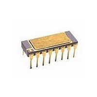
ISOLAT 1.5KVDC 4CH OPEN 16SMD GW
Manufacturer
Avago Technologies US Inc.
Datasheet
1.6N139-500E.pdf
(12 pages)
Specifications of 6N140A#300
Output Type
Open Collector
Package / Case
16-SMD, Gull Wing
Voltage - Isolation
1500VDC
Number Of Channels
4, Unidirectional
Current - Output / Channel
40mA
Data Rate
100KBd
Propagation Delay High - Low @ If
30µs @ 500µA
Current - Dc Forward (if)
10mA
Input Type
DC
Mounting Type
Surface Mount, Gull Wing
Logic Gate Type
Inverter
Configuration
4 Channel
Current Transfer Ratio
1500 %
Maximum Propagation Delay Time
100 us
Maximum Forward Diode Voltage
1.8 V
Maximum Reverse Diode Voltage
5 V
Maximum Forward Diode Current
5 mA
Maximum Continuous Output Current
40 mA
Maximum Power Dissipation
200 mW
Maximum Operating Temperature
+ 125 C
Minimum Operating Temperature
- 55 C
Output Device
Darlington With Base
Number Of Elements
4
Reverse Breakdown Voltage
5V
Forward Voltage
1.7V
Forward Current
10mA
Package Type
PDIP
Power Dissipation
200mW
Pin Count
16
Mounting
Surface Mount
Operating Temp Range
-55C to 125C
Operating Temperature Classification
Military
Lead Free Status / RoHS Status
Contains lead / RoHS non-compliant
Lead Free Status / RoHS Status
Lead free / RoHS Compliant, Contains lead / RoHS non-compliant
Available stocks
Company
Part Number
Manufacturer
Quantity
Price


Absolute Maximum Ratings
8 Pin Ceramic DIP Single Channel Schematic
CATHODE
ESD Classification
(MIL-STD-883, Method 3015)
Recommended Operating Conditions
6
Parameter
Storage Temperature
Operating Temperature
Case Temperature
Junction Temperature
Lead Solder Temperature
Output Current (each channel)
Output Voltage (each channel)
Supply Voltage
Output Power Dissipation (each channel)
Peak Input Current (each channel, <1 ms duration)
Average Input Current (each channel)
Reverse Input Voltage (each channel)
Package Power Dissipation (each channel)
HCPL-5700/01/0K and 6730/31/3K
6N140A, 6N140A/883B, HCPL-177K,
HCPL-6750/51/5K and HCPL-5730/31/3K
Parameter
Input Voltage, Low Level (Each Channel)
Input Current, High Level (Each Channel)
Supply Voltage
Output Voltage
ANODE
V
F
+
2
–
3
I
F
V
8
CC
I
CC
I
O
6
5
V
GND
O
Symbol
V
I
V
V
F(ON)
F(OFF)
CC
O
Symbol
T
T
T
T
I
V
V
I
V
P
O
F
A
C
J
S
D
O
CC
R
(
(Dot), Class 3
Min.
-65
-55
-0.5
-0.5
Min.
0.5
2.0
2.0
), Class 2
Max.
+150
+125
+170
+175
260 for 10 sec
40
20
20
50
20
10
5
200
Max.
5
18
18
0.8
Units
°C
°C
°C
°C
°C
mA
V
V
mW
mA
mA
V
mW
Units
mA
V
V
V
1
1
2
3
Notes
Related parts for 6N140A#300
Image
Part Number
Description
Manufacturer
Datasheet
Request
R

Part Number:
Description:
OPTOCOUPLER 4CH SEALED 16-DIP
Manufacturer:
Avago Technologies US Inc.
Datasheet:

Part Number:
Description:
ISOLAT 1.5KVDC 4CH OPEN 16SMD BJ
Manufacturer:
Avago Technologies US Inc.
Datasheet:

Part Number:
Description:
ISOLAT 1.5KVDC 4CH OPEN 16SMD BJ
Manufacturer:
Avago Technologies US Inc.
Datasheet:

Part Number:
Description:
OPTOCOUPLER HIGH GAIN 16-DIP
Manufacturer:
Avago Technologies US Inc.
Datasheet:
Part Number:
Description:
OPTOCOUPLER HIGH GAIN HERM 16DIP
Manufacturer:
Avago Technologies US Inc.
Datasheet:
Part Number:
Description:
OPTOCOUPLER HIGH GAIN HERM 16DIP
Manufacturer:
Avago Technologies US Inc.
Datasheet:
Part Number:
Description:
OPTOCOUPLER HIGH GAIN HERM 16DIP
Manufacturer:
Avago Technologies US Inc.
Datasheet:
Part Number:
Description:
OPTOCOUPLER HIGH GAIN HERM 16DIP
Manufacturer:
Avago Technologies US Inc.
Datasheet:

Part Number:
Description:
OPTOCOUPLER HIGH GAIN HERM 16DIP
Manufacturer:
Avago Technologies US Inc.
Datasheet:

Part Number:
Description:
OPTOCOUPLER GATE DRV 2A 16-SOIC
Manufacturer:
Avago Technologies US Inc.
Datasheet:
Part Number:
Description:
OPTOCOUPLER 2CH 2.5A 16-SOIC
Manufacturer:
Avago Technologies US Inc.
Datasheet:

Part Number:
Description:
OPTOCOUPLER GATE DRV 0.4A 16SOIC
Manufacturer:
Avago Technologies US Inc.
Datasheet:

Part Number:
Description:
OPTOCOUPLER 2.0A 250KHZ 8-DIP
Manufacturer:
Avago Technologies US Inc.
Datasheet:

Part Number:
Description:
OPTOCOUPLER 2.0A 250KHZ GW 8-SMD
Manufacturer:
Avago Technologies US Inc.
Datasheet:

Part Number:
Description:
OPTOCOUPLER 2CH 15MBD 3.3V 8SOIC
Manufacturer:
Avago Technologies US Inc.
Datasheet: