6N139-000E Avago Technologies US Inc., 6N139-000E Datasheet - Page 7
6N139-000E
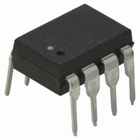
Manufacturer Part Number
6N139-000E
Description
OPTOCOUPLER DARL-OUT 8-DIP
Manufacturer
Avago Technologies US Inc.
Type
Analogr
Datasheets
1.6N139-500E.pdf
(16 pages)
2.6N139-500E.pdf
(12 pages)
3.6N139-000E.pdf
(14 pages)
4.6N139-000E.pdf
(16 pages)
Specifications of 6N139-000E
Input Type
DC
Package / Case
8-DIP (0.300", 7.62mm)
Voltage - Isolation
3750Vrms
Number Of Channels
1, Unidirectional
Current - Output / Channel
60mA
Data Rate
100KBd
Propagation Delay High - Low @ If
5µs @ 500µA
Current - Dc Forward (if)
20mA
Output Type
Open Collector
Mounting Type
Through Hole
Isolation Voltage
3750 Vrms
Maximum Fall Time
25 us
Maximum Rise Time
60 us
Minimum Forward Diode Voltage
1.25 V
Output Device
Darlington With Base
Configuration
1 Channel
Current Transfer Ratio
5000 %
Maximum Baud Rate
100 KBps
Maximum Forward Diode Voltage
1.7 V
Maximum Reverse Diode Voltage
5 V
Maximum Input Diode Current
20 mA
Maximum Power Dissipation
135 mW
Maximum Operating Temperature
+ 70 C
Minimum Operating Temperature
0 C
Package Type
8-Pin DIP
No. Of Channels
1
Optocoupler Output Type
Photodarlington
Input Current
12mA
Output Voltage
18V
Opto Case Style
DIP
No. Of Pins
8
Ctr Max
5000%
Ctr Min
400%
Rohs Compliant
Yes
Lead Free Status / RoHS Status
Lead free / RoHS Compliant
Lead Free Status / RoHS Status
Lead free / RoHS Compliant, Lead free / RoHS Compliant
Other names
516-1601-5
Available stocks
Company
Part Number
Manufacturer
Quantity
Price
Company:

Part Number:
6N139-000E
Manufacturer:
AVG
Quantity:
4 684
Part Number:
6N139-000E
Manufacturer:
AVAGO/安华高
Quantity:
20 000


Recommended Pb-Free IR Profile
Regulatory Information
The 6N139/138, HCNW139/138, and HCPL-0701/0700 have been approved by the following organizations:
UL
Recognized under UL 1577, Component Recognition
Program, File E55361.
CSA
Approved under CSA Component Acceptance Notice
#5, File CA 88324.
7
Insulation and Safety Related Specifications
Option 300 - surface mount classification is Class A in accordance with CECC 00802.
Parameter
Minimum External
Air Gap (External
Clearance)
Minimum External
Tracking (External
Creepage)
Minimum Internal
Plastic Gap
(Internal Clearance)
Minimum Internal
Tracking (Internal
Creepage)
Tracking Resistance
(Comparative
Tracking Index)
Isolation Group
T
T
smax
smin
25
T
T
p
L
217 °C
150 - 200 °C
t 25 °C to PEAK
60 to 180 SEC.
PREHEAT
3 °C/SEC. MAX.
t
s
Symbol
L(101)
L(102)
RAMP-UP
CTI
* 260 +0/-5 °C
TIME
8-Pin DIP
(300 Mil)
Value
0.08
200
7.1
7.4
NA
IIIa
t
t
L
p
TIME WITHIN 5 °C of ACTUAL
PEAK TEMPERATURE
15 SEC.
60 to 150 SEC.
Value
SO-8
0.08
200
NA
RAMP-DOWN
6 °C/SEC. MAX.
4.9
4.8
IIIa
IEC/EN/DIN EN 60747-5-2
Approved under
IEC 60747-5-2:1997 + A1:2002
EN 60747-5-2:2001 + A1:2002
DIN EN 60747-5-2 (VDE 0884 Teil 2):2003-01
(HCNW139/138 only)
Widebody
(400 Mil)
Value
10.0
200
9.6
1.0
4.0
IIIa
NOTES:
THE TIME FROM 25 °C to PEAK
TEMPERATURE = 8 MINUTES MAX.
T
NOTE: NON-HALIDE FLUX SHOULD BE USED.
* RECOMMENDED PEAK TEMPERATURE FOR
smax
WIDEBODY 400mils PACKAGE IS 245 °C
Units
Volts
mm
mm
mm
mm
= 200 °C, T
Conditions
Measured from input terminals
to output terminals, shortest
distance through air.
Measured from input terminals
to output terminals, shortest
distance path along body.
Through insulation distance,
conductor to conductor, usually
the direct distance between the
photoemitter and photodetector
inside the optocoupler cavity.
Measured from input terminals
to output terminals, along
internal cavity.
DIN IEC 112/VDE 0303 Part 1
Material Group
(DIN VDE 0110, 1/89, Table 1)
smin
= 150 °C
Related parts for 6N139-000E
Image
Part Number
Description
Manufacturer
Datasheet
Request
R

Part Number:
Description:
OPTOCOUPLER 1CH 0.5MA 8-SMD
Manufacturer:
Avago Technologies US Inc.
Datasheet:
Part Number:
Description:
OPTOCOUPLER 1CH 0.5MA UL 8-SMD
Manufacturer:
Avago Technologies US Inc.
Datasheet:
Part Number:
Description:
OPTOCOUPLER 1CH 0.5MA VDE 8-SMD
Manufacturer:
Avago Technologies US Inc.
Datasheet:

Part Number:
Description:
OPTOCOUPLER 1CH 0.5MA UL 8-DIP
Manufacturer:
Avago Technologies US Inc.
Datasheet:

Part Number:
Description:
OPTOCOUPLER DARL-OUT 8-DIP
Manufacturer:
Avago Technologies US Inc.
Datasheet:

Part Number:
Description:
OPTOCOUPLER, DARLINGTON, 3750VRMS
Manufacturer:
Avago Technologies US Inc.
Datasheet:

Part Number:
Description:
OPTOCOUPLER 1CH 0.5MA VDE 8-SMD
Manufacturer:
Avago Technologies US Inc.
Datasheet:
Part Number:
Description:
OPTOCOUPLER 1CH 0.5MA UL 8-SMD
Manufacturer:
Avago Technologies US Inc.
Datasheet:
Part Number:
Description:
OPTOCOUPLER 1CH 0.5MA UL 8-DIP
Manufacturer:
Avago Technologies US Inc.
Datasheet:
Part Number:
Description:
OPTOCOUPLER 1CH 0.5MA 8-SMD GW
Manufacturer:
Avago Technologies US Inc.
Datasheet:
Part Number:
Description:
OPTOCOUPLER 1CH 0.5MA 8-SMD GW
Manufacturer:
Avago Technologies US Inc.
Datasheet:
Part Number:
Description:
OPTOCOUPLER 1CH 0.5MA UL 8SMD GW
Manufacturer:
Avago Technologies US Inc.
Datasheet:
Part Number:
Description:
OPTOCOUPLER(100KBD),VDE
Manufacturer:
Avago Technologies US Inc.
Datasheet:
Part Number:
Description:
Darlington-NPN-Output Dc-Input Optocoupler,1-CHANNEL,3.75kV ISOLATION,SO
Manufacturer:
Avago Technologies US Inc.
Datasheet:
Part Number:
Description:
Optocoupler(100kBd),IEC+LF
Manufacturer:
Avago Technologies US Inc.
Datasheet: