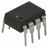
HCPL-3120-000E Avago Technologies US Inc., HCPL-3120-000E Datasheet - Page 26

HCPL-3120-000E
Manufacturer Part Number
HCPL-3120-000E
Description
OPTOCOUPLER IGBT DRIV 2.5A 8-DIP
Manufacturer
Avago Technologies US Inc.
Type
Analogr
Specifications of HCPL-3120-000E
Output Type
Gate Driver
Package / Case
8-DIP (0.300", 7.62mm)
Voltage - Isolation
3750Vrms
Number Of Channels
1, Unidirectional
Current - Output / Channel
2.5A
Propagation Delay High - Low @ If
300ns @ 7mA ~ 16mA
Current - Dc Forward (if)
25mA
Input Type
DC
Mounting Type
Through Hole
Configuration
1 Channel
Isolation Voltage
5000 Vrms
Maximum Propagation Delay Time
500 ns
Maximum Forward Diode Voltage
1.8 V
Minimum Forward Diode Voltage
1.2 V
Maximum Reverse Diode Voltage
5 V
Maximum Forward Diode Current
7 mA
Maximum Power Dissipation
295 mW
Maximum Operating Temperature
+ 100 C
Minimum Operating Temperature
- 40 C
Package Type
8-Pin DIP
No. Of Channels
1
Optocoupler Output Type
Gate Drive
Input Current
16mA
Output Voltage
30V
Opto Case Style
DIP
No. Of Pins
8
Common Mode Ratio
15 KV/uS
Rohs Compliant
Yes
Lead Free Status / RoHS Status
Lead free / RoHS Compliant
Lead Free Status / RoHS Status
Lead free / RoHS Compliant, Lead free / RoHS Compliant
Other names
516-1476-5
Available stocks
Company
Part Number
Manufacturer
Quantity
Price
Company:
Part Number:
HCPL-3120-000E
Manufacturer:
AVAGO
Quantity:
24 000
Company:
Part Number:
HCPL-3120-000E
Manufacturer:
AVAGO
Quantity:
10 000
Part Number:
HCPL-3120-000E
Manufacturer:
AVAGO/安华高
Quantity:
20 000
Part Number:
HCPL-3120-000E/HCPL3120-000E
Manufacturer:
AVAGO/安华高
Quantity:
20 000
V
V
IPM Dead Time and Propagation
Delay Specifications. (Discussion
applies to HCPL-3120, HCPL-J312,
and HCNW3120)
Figure 35. Minimum LED skew for zero dead time.
Figure 37. Thermal derating curve, dependence of safety limiting value with case temperature
per IEC/EN/DIN EN 60747-5-2.
I
I
OUT1
OUT2
LED1
LED2
*PDD = PROPAGATION DELAY DIFFERENCE
NOTE: FOR PDD CALCULATIONS THE PROPAGATION DELAYS
ARE TAKEN AT THE SAME TEMPERATURE AND TEST CONDITIONS.
800
700
600
500
400
300
200
100
0
0
HCPL-3120 OPTION 060/HCPL-J312
T
25
S
– CASE TEMPERATURE – °C
50
P
I
OPTION 060
I
75 100
S
S
S
(mA) FOR HCPL-3120
(mA) FOR HCPL-J312
(mW)
PDD* MAX = (t
t
PHL MAX
Q2 OFF
Q1 ON
125
150 175
t
PLH MIN
PHL
- t
200
PLH
)
MAX
= t
Q1 OFF
Q2 ON
1000
PHL MAX
900
800
700
600
500
400
300
200
100
0
0
T
25
S
- t
– CASE TEMPERATURE – °C
PLH MIN
50
P
I
S
HCNW3120
S
(mA)
(mW)
75
*PDD = PROPAGATION DELAY DIFFERENCE
NOTE: FOR DEAD TIME AND PDD CALCULATIONS ALL PROPAGATION
DELAYS ARE TAKEN AT THE SAME TEMPERATURE AND TEST CONDITIONS.
Figure 36. Waveforms for dead time.
V
V
100
I
I
OUT1
OUT2
LED1
LED2
125
150
175
(t
PHL-
PDD* MAX
Q1 ON
Q2 OFF
t
t
PHL MIN
PHL MAX
t
PLH
)
MAX
MAXIMUM DEAD TIME
(DUE TO OPTOCOUPLER)
= (t
= (t
= PDD* MAX – PDD* MIN
PHL MAX
PHL MAX
t
MIN
PLH
t
PLH MAX
- t
- t
PHL MIN
PLH MIN
) + (t
) – (t
Q1 OFF
PLH MAX
PHL MIN
Q2 ON
- t
- t
PLH MAX
PLH MIN
)
)


