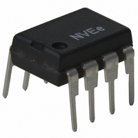
IL610-2E NVE, IL610-2E Datasheet - Page 10

IL610-2E
Manufacturer Part Number
IL610-2E
Description
ISOLATOR PASSIVE INPUT HS 8DIP
Manufacturer
NVE
Series
IsoLoop®r
Specifications of IL610-2E
Inputs - Side 1/side 2
1/0
Number Of Channels
1
Isolation Rating
2500Vrms
Voltage - Supply
3 V ~ 5.5 V
Data Rate
100Mbps
Propagation Delay
12ns
Output Type
CMOS
Package / Case
8-DIP
Operating Temperature
-40°C ~ 85°C
No. Of Channels
1
Supply Current
2mA
Supply Voltage Range
3V To 5.5V
Digital Ic Case Style
DIP
No. Of Pins
8
Operating Temperature Range
-40°C To +85°C
Operating
RoHS Compliant
Base Number
610
Rohs Compliant
Yes
Lead Free Status / RoHS Status
Lead free / RoHS Compliant
Other names
390-1076-5
The In- terminal I is connected via a 1 kΩ current
limiting resistor to the supply rail and the input is
connected to the In+ terminal. Assume the supply
voltage is +5 V and the input signal is a 5 V CMOS
signal. A 1 kΩ resistor is selected to limit the current
into the coil to 5 mA. For the purpose of this
illustration we will ignore the coil resistance. When a
logic high (+5 V) is applied to the input, the current
through the coil is zero. When the input is a logic
low ( 0 V), approximately 5 mA flows from the In-
side through the coil to the In+ side. Figure 3 shows
that the device will transition to both logic states
easily under these conditions. Assume that the 5 V
rail is now sitting at 5.5 V and the CMOS input
signal is loaded so that its high level is only 4.5 V.
When a logic high (4.5 V) now appears on the input,
there is still a current of -1mA flowing through the
coil. Referring to Figure 3 shows that the device is
getting close to the off-state threshold of
-1.5 mA and actually exceeds the specification of
-0.8 mA for this logic level. Some intermittent
operation may be expected in this case. The
designer must ensure that the difference between the
logic high voltage and the power supply voltage is
such that the residual current in the coil is lower
than 0.8 mA.
In the inverting configuration the design problem is
the same as the standard logic problem. The signal
into the coil is now differential with respect to
ground. The designer must ensure that the difference
between the logic low voltage and the ground point
to which the coil is connected is such that the
residual current in the coil is lower than
0.8 mA. The usual design precautions regarding
ground bounce should also be taken into
consideration.
The IL612 and IL614 devices have some inputs which do not offer non-inverting operation. The power supply to the device is
hardwired internally to the coil In- input. Therefore it is important to make sure that the power supply to the isolator is at the same
voltage as the power supply to the source of the input logic signal.
The IL600 devices are simple to use as long as it is remembered that the application must allow sufficient current (-5 mA) to flow
in the coil for an output logic low state, and close to zero current (-0.8 mA to 0 mA) to flow for an output logic high state.
Magnetic Field Booster
In all applications, it is possible to boost the signal seen by the GMR sensor. This can be of benefit in high temperature
applications or in cases where differential currents of 5mA can not always be guaranteed. A small capacitor (see page 5) placed
across the current limiting resistor will effectively boost instantaneous current through the coil at the point of signal transition. The
resultant magnetic field has the effect of pushing the GMR bridge output through the comparator threshold voltage with reduced
propagation delay and improved pulse width distortion. Figure 5 shows how the capacitor is connected in the case of the IL610.
Note that the capacitor can be used in both inverting and non-inverting modes of operation. The use of the capacitor gives a great
deal of design headroom and can usually eliminate design concerns related to temperature range and power supply fluctuation. In
3.3 V applications the capacitor must be used. In 5 V applications where t
Figure 4. Inverting and Non-Inverting circuits
Inverting Circuit
Inverting Circuit
Non-Inverting Circuit
Non-Inverting Circuit
Data In
Data In
10
Data In
Data In
1K
1K
r
, t
GND
GND
f
< 1
1K
1K
GND
GND
1
1
µ
3
3
2
2
+5 V
+5 V
s use of the capacitor is highly recommended.
1
1
IL610
IL610
+
+
-
-
2
2
3
3
+
+
IL610
IL610
-
-
GND
GND
IL600 Series
8
8
7
7
6
6
5
5
GND
GND
C
C
2
2
8
8
7
7
6
6
5
5
Data Out
Data Out
1
1
Note. C
Note. C
C
C
2
2
Note. C
Note. C
Data Out
Data Out
1
1
V
V
DD
DD
1
1
V
V
1
1
is 47 nF ceramic.
is 47 nF ceramic.
DD
DD
is 47 nF ceramic.
is 47 nF ceramic.


